Difference between revisions of "Kerr - July 15, 2016"
Jump to navigation
Jump to search
| Line 1: | Line 1: | ||
At this point, everything is set up. All that's left is for me to actually figure out how everything works. | At this point, everything is set up. All that's left is for me to actually figure out how everything works. | ||
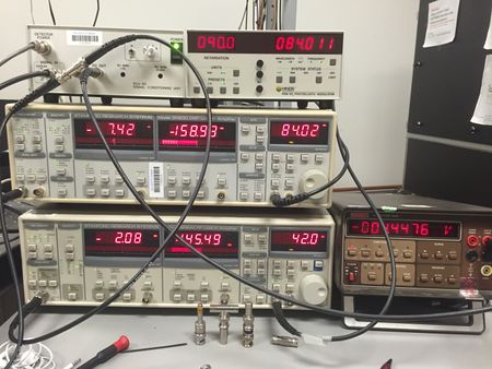
| − | [[file:Lockinamp.jpeg|thumb|Here we see the two lock-in Amplifiers, the Single Conditioning Unit, the PEM modulator, and a digital Multimeter.]] | + | [[file:Lockinamp.jpeg|thumb|upright=1.5|Here we see the two lock-in Amplifiers, the Single Conditioning Unit, the PEM modulator, and a digital Multimeter.]] |
* We decided to initially go with the polarizer-foil-pem-analyzer-diode set up. (there is an alternate setup in the PEM manual in section 3c | * We decided to initially go with the polarizer-foil-pem-analyzer-diode set up. (there is an alternate setup in the PEM manual in section 3c | ||
Revision as of 08:26, 18 July 2016
At this point, everything is set up. All that's left is for me to actually figure out how everything works.
- We decided to initially go with the polarizer-foil-pem-analyzer-diode set up. (there is an alternate setup in the PEM manual in section 3c
- We learned that 2 Lock-in Amplifiers are necessary in order to lock on to two different frequencies
- The lock-in Amplifier reports V(rms) as opposed to a peak Voltage
- Great theory resources here when it comes to PEM operations http://www.hindsinstruments.com/knowledge-center/product-document-library/product-literature/
