Difference between revisions of "Bubble Chamber Beam Test September 2015"
Jump to navigation
Jump to search
| Line 41: | Line 41: | ||
* Measuring rates from <sup>18</sup>O(γ,α)<sup>14</sup>C: | * Measuring rates from <sup>18</sup>O(γ,α)<sup>14</sup>C: | ||
| − | # Now the chamber is at | + | # Now the chamber is at the new pressure |
# Start with beam at K.E. 7.2 MeV | # Start with beam at K.E. 7.2 MeV | ||
# Increase beam K.E. by 0.2 MeV steps all the way to 9.2 MeV | # Increase beam K.E. by 0.2 MeV steps all the way to 9.2 MeV | ||
| + | # Adjust beam current to maintain a bubble rate of few per minute | ||
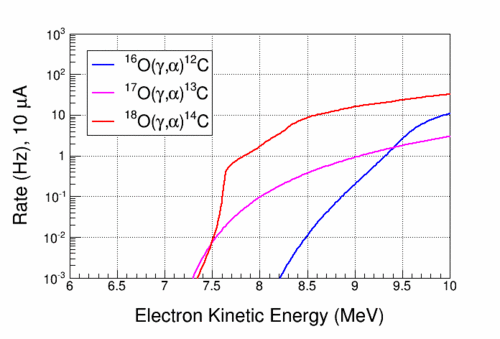
# Reproduce the overall rate from oxygen isotopes shown above | # Reproduce the overall rate from oxygen isotopes shown above | ||
# Note the change in slope of rates vs. beam K.E. and the sharp kink around 7.6 MeV | # Note the change in slope of rates vs. beam K.E. and the sharp kink around 7.6 MeV | ||
| Line 49: | Line 50: | ||
* Measuring <sup>18</sup>O(γ,α)<sup>14</sup>C cross section: | * Measuring <sup>18</sup>O(γ,α)<sup>14</sup>C cross section: | ||
| − | # Start with beam at K.E. 7. | + | # Start with beam at K.E. 7.4 MeV |
| − | # Increase beam K.E. by 0. | + | # Increase beam K.E. by 0.1 MeV steps all the way to 8.4 MeV |
| + | # Adjust beam current to maintain a bubble rate of few per minute | ||
# Perform Penfold-Leiss unfolding | # Perform Penfold-Leiss unfolding | ||
| + | |||
| + | |||
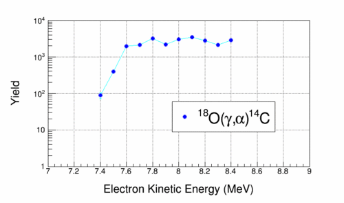
| + | # The expected yield is shown in the following figure: | ||
| + | |||
| + | [[file:csO18_Yield_Brem_bg.gif||500px|]] | ||
| + | |||
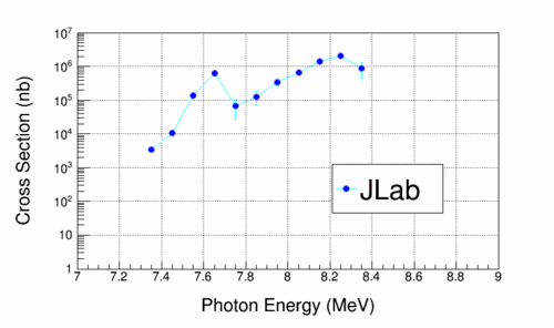
| + | # The measured cross section using Penfold-Leiss unfolding is shown in the following figure: | ||
| + | |||
| + | [[file:csO18_Brem_Unfold_bg.gif||500px|]] | ||
Revision as of 13:50, 6 September 2015
Run Plan
- Chamber is filled with natural N2O
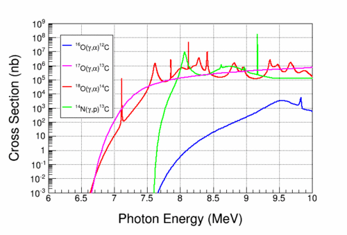
- Cross sections:
The cross sections are shown in the following figure:
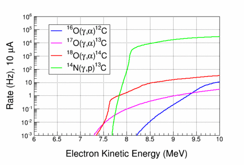
- Expected rates:
The expected rates are calculated with 3 cm cell thickness and thin radiator.
- The expected rates are shown in the following figure:
- The expected rates from oxygen isotopes are shown in the following figure:
- Run Plan:
- Suppression of 14N(γ,p)13C events:
- Determine an initial pressure and temperature with no beam
- Start with beam at K.E. 6.5 MeV
- Increase beam K.E. by 0.2 MeV steps all the way to 8.5 MeV
- Adjust beam current to maintain a bubble rate of few per minute
- Reproduce the overall rate shown above
- At K.E. of 8.5 MeV, increase the chamber threshold by increasing the pressure. Suppress the 14N(γ,p)13C events.
- Once 14N(γ,p)13C is suppressed, the rate should drop by three orders of magnitude
- Measuring rates from 18O(γ,α)14C:
- Now the chamber is at the new pressure
- Start with beam at K.E. 7.2 MeV
- Increase beam K.E. by 0.2 MeV steps all the way to 9.2 MeV
- Adjust beam current to maintain a bubble rate of few per minute
- Reproduce the overall rate from oxygen isotopes shown above
- Note the change in slope of rates vs. beam K.E. and the sharp kink around 7.6 MeV
- Measuring 18O(γ,α)14C cross section:
- Start with beam at K.E. 7.4 MeV
- Increase beam K.E. by 0.1 MeV steps all the way to 8.4 MeV
- Adjust beam current to maintain a bubble rate of few per minute
- Perform Penfold-Leiss unfolding
- The expected yield is shown in the following figure:
- The measured cross section using Penfold-Leiss unfolding is shown in the following figure:
