Difference between revisions of "200kV High Voltage Power Supply & Controls"
| Line 10: | Line 10: | ||
:[[Media:cable quote.pdf]] | :[[Media:cable quote.pdf]] | ||
:[[Media:Matsusada_comm_troubleshooting.txt]] | :[[Media:Matsusada_comm_troubleshooting.txt]] | ||
| + | |||
| + | ;Power Supply Settings | ||
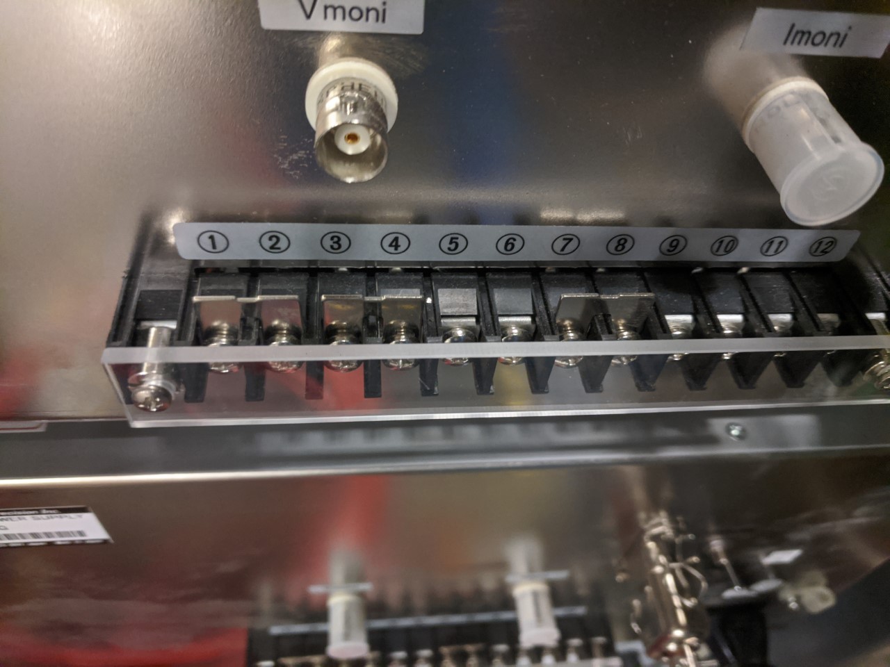
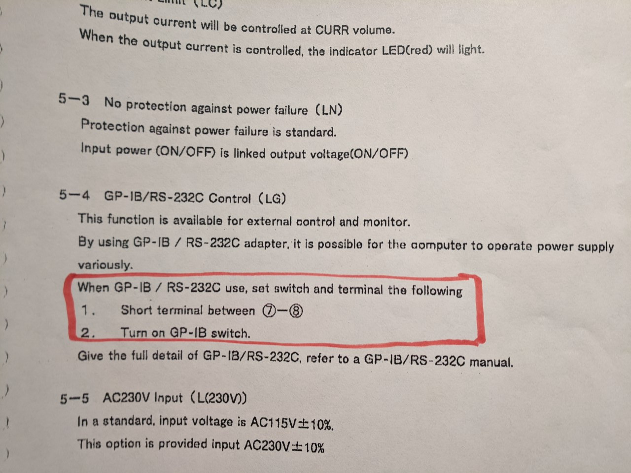
Terminals 1-2, 3-4 and 7-8 on the rear of the Matsusada power supplies should be jumpered for correct operation of our application. 1-2 is to allow remote HV enabling (or rather a switch-based disabling, which we don't use). 7-8 allows for remote operation of the supplies. | Terminals 1-2, 3-4 and 7-8 on the rear of the Matsusada power supplies should be jumpered for correct operation of our application. 1-2 is to allow remote HV enabling (or rather a switch-based disabling, which we don't use). 7-8 allows for remote operation of the supplies. | ||
| Line 16: | Line 18: | ||
[[File:Remote operation jumper.jpg]] | [[File:Remote operation jumper.jpg]] | ||
| + | |||
| + | ;Controller Settings | ||
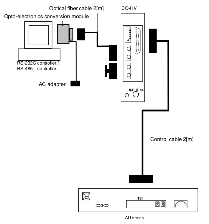
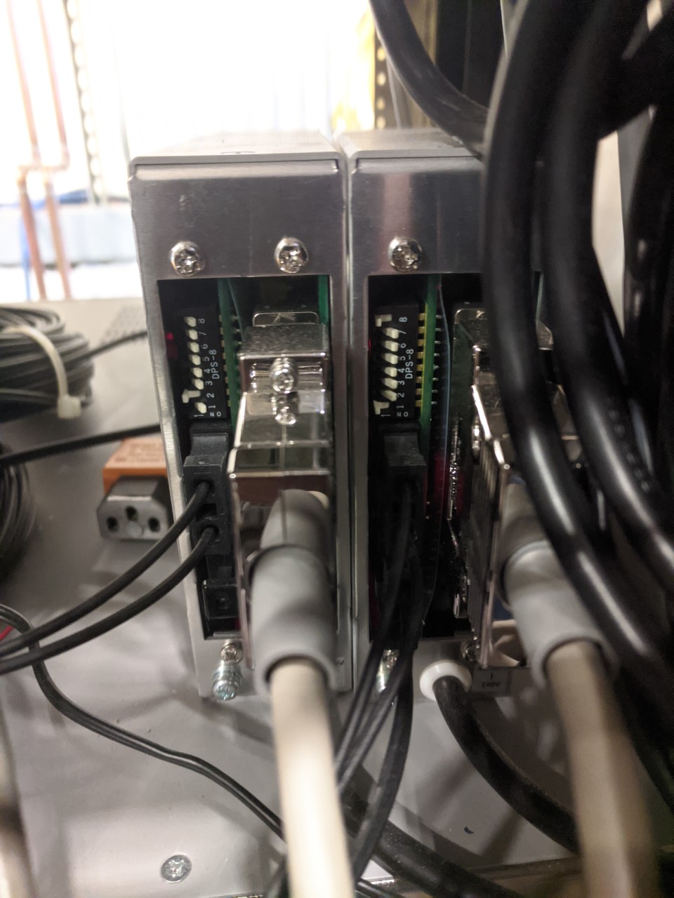
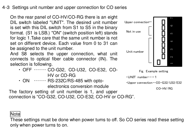
DIP switches on the rear of the CO-HV controllers need to be set correctly. Switches 1-5 define the unit address. We use address 1 for the positive supply of each Wien, address 2 for the negative supply. Switch 8 defines the 'upper connection' of the optical link, essentially the system master. Set switch 8 on the unit that is addressed 1. | DIP switches on the rear of the CO-HV controllers need to be set correctly. Switches 1-5 define the unit address. We use address 1 for the positive supply of each Wien, address 2 for the negative supply. Switch 8 defines the 'upper connection' of the optical link, essentially the system master. Set switch 8 on the unit that is addressed 1. | ||
| + | |||
[[File:CO-HV hookup.png]] | [[File:CO-HV hookup.png]] | ||
[[File:Controller switches.jpg]] | [[File:Controller switches.jpg]] | ||
| Line 23: | Line 28: | ||
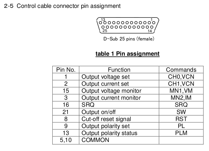
Here is the pinout of the control cable that connects the CO-HV controller to the power supply: | Here is the pinout of the control cable that connects the CO-HV controller to the power supply: | ||
| + | |||
[[File:Control cable.png]] | [[File:Control cable.png]] | ||
Revision as of 07:11, 7 May 2021
This page contains information about the high voltage power supply controls used at CEBAF and UITF.
- Power Supplies and Controller
- +/- 30 kV HVPS [1] AE-30P1-LG (+30kV) and AE-30N1-LG (-30kV) File:Matsusada AE series spec sheet.pdf
- Media:Matsusada PS output voltage accuracy.pdf
- Media:Matsusada PS quote JeffersonLabAE09062017-1.pdf
- Matsusda HV power supplies operations manual Media:Matsusada AE 30kV PS series manual.pdf
- Media:CO series communication controller.pdf
- Media:CO series REV 0.4.pdf
- Media:cable quote.pdf
- Media:Matsusada_comm_troubleshooting.txt
- Power Supply Settings
Terminals 1-2, 3-4 and 7-8 on the rear of the Matsusada power supplies should be jumpered for correct operation of our application. 1-2 is to allow remote HV enabling (or rather a switch-based disabling, which we don't use). 7-8 allows for remote operation of the supplies.
- Controller Settings
DIP switches on the rear of the CO-HV controllers need to be set correctly. Switches 1-5 define the unit address. We use address 1 for the positive supply of each Wien, address 2 for the negative supply. Switch 8 defines the 'upper connection' of the optical link, essentially the system master. Set switch 8 on the unit that is addressed 1.
Here is the pinout of the control cable that connects the CO-HV controller to the power supply:
