Difference between revisions of "2020 Steel Shield Experiments at GTS"
Jump to navigation
Jump to search
| (One intermediate revision by the same user not shown) | |||
| Line 19: | Line 19: | ||
== Experimental Procedure == | == Experimental Procedure == | ||
| − | # Install Newport silicon photo-diode with power meter on angled view port | + | # Install Newport silicon photo-diode with power meter on angled view port Can use a cyan filter to block the red-orange light from cathode (would need to look up the transmittance of the filter to ensure the short-wavelength spectral lines can pass through it) |
#*Note that ideally, a "continuous" light measurement would need to be taken to see the rise and fall of the recombination light when the e-beam is turned on and off. Ideally, the light measurement would be compared with other parameters in MyaPlot. | #*Note that ideally, a "continuous" light measurement would need to be taken to see the rise and fall of the recombination light when the e-beam is turned on and off. Ideally, the light measurement would be compared with other parameters in MyaPlot. | ||
# Cover the photo-diode set up with tarp or equivalent opaque material to block out excess sources of light | # Cover the photo-diode set up with tarp or equivalent opaque material to block out excess sources of light | ||
| Line 43: | Line 43: | ||
* See [https://logbooks.jlab.org/entry/3858197] and [https://logbooks.jlab.org/entry/3858205] | * See [https://logbooks.jlab.org/entry/3858197] and [https://logbooks.jlab.org/entry/3858205] | ||
| − | * Photodiode Info: [https://www.newport.com/p/818-SL--DB | + | * Photodiode Info: [https://www.newport.com/p/818-SL--DB] |
== Relevant Calculations/Tech Notes/Useful Links == | == Relevant Calculations/Tech Notes/Useful Links == | ||
Latest revision as of 16:08, 7 December 2020
Info on proposed steel shield experiments using the T-Gun at GTS
Previous Parameters
- Gun Voltage: 100 kV
- Gun Solenoid Current: 150 A. Experiments varied the current between 30 A and 150 A
- Anode Voltage: 1 kV (961 V). Experiments varied the anode bias voltage between 388 V and 961 V
- Beam Current: 100-500 uA
- Gun Vacuum Levels: Usually > 1e-9 A ion pump current at the gun
Proposed Parameters
- Gun Voltage: 90 kV (should be fine for experiment purposes)
- Gun Solenoid Current: 150 A
- Anode Voltage: 1 kV
- Beam Current: 500 uA or higher (to ensure sufficient measured intensity from recombining ions)
- Gun Vacuum Levels: Higher pressure -> higher ion production rate -> higher number of recombining ions -> higher light intensity and higher probability of measuring recombination light above background
Experimental Procedure
- Install Newport silicon photo-diode with power meter on angled view port Can use a cyan filter to block the red-orange light from cathode (would need to look up the transmittance of the filter to ensure the short-wavelength spectral lines can pass through it)
- Note that ideally, a "continuous" light measurement would need to be taken to see the rise and fall of the recombination light when the e-beam is turned on and off. Ideally, the light measurement would be compared with other parameters in MyaPlot.
- Cover the photo-diode set up with tarp or equivalent opaque material to block out excess sources of light
- Take baseline light measurement with e-beam ON (and cathode ON)
- Set anode to +1 kV bias. Take light measurement.
- Set GS to 150 A. Take light measurement
- Set gun HV to 90 kV. Take light measurement
- Run e-beam with proposed parameters (above). Take light measurement. Note that this would be the first step that we'd expect to see measurable light above background due to recombination. The measured light should rise and then plateau while the e-beam is on, corresponding to the trap "filling" and reaching equilibrium.
- Turn e-beam off. Take light measurement. The measured light should (slowly) fall back to background.
- Turn off HV. Take light measurement.
- In increments of 10A, bring GS back to 0A. Take light measurement, provided light is seen in the above steps
- Return anode bias to 0V. Take final light measurement (should be equal to baseline measurement)
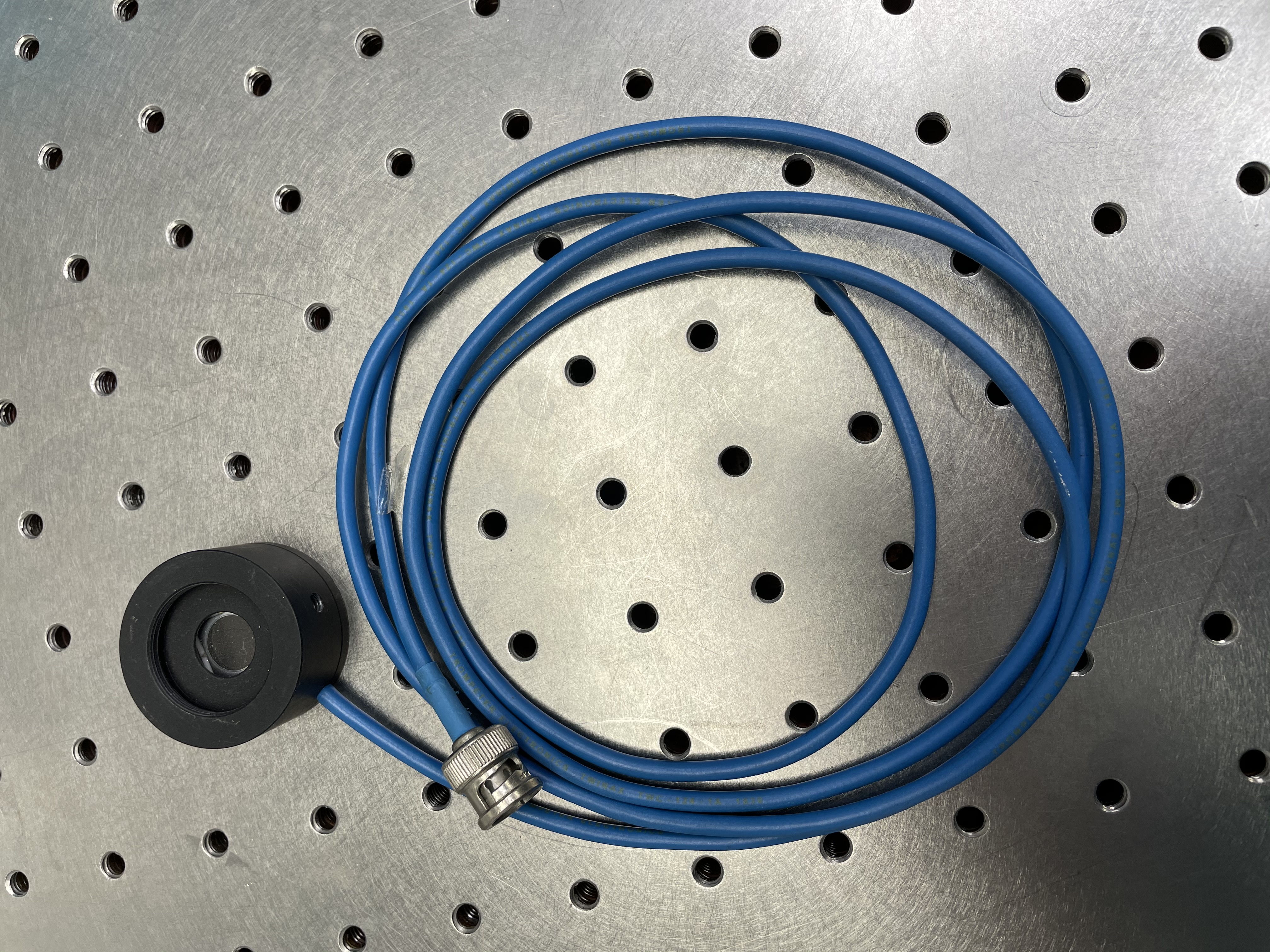
Photo-diode Pics:
- media:IMG 7291.JPG - Photo-diode & cord
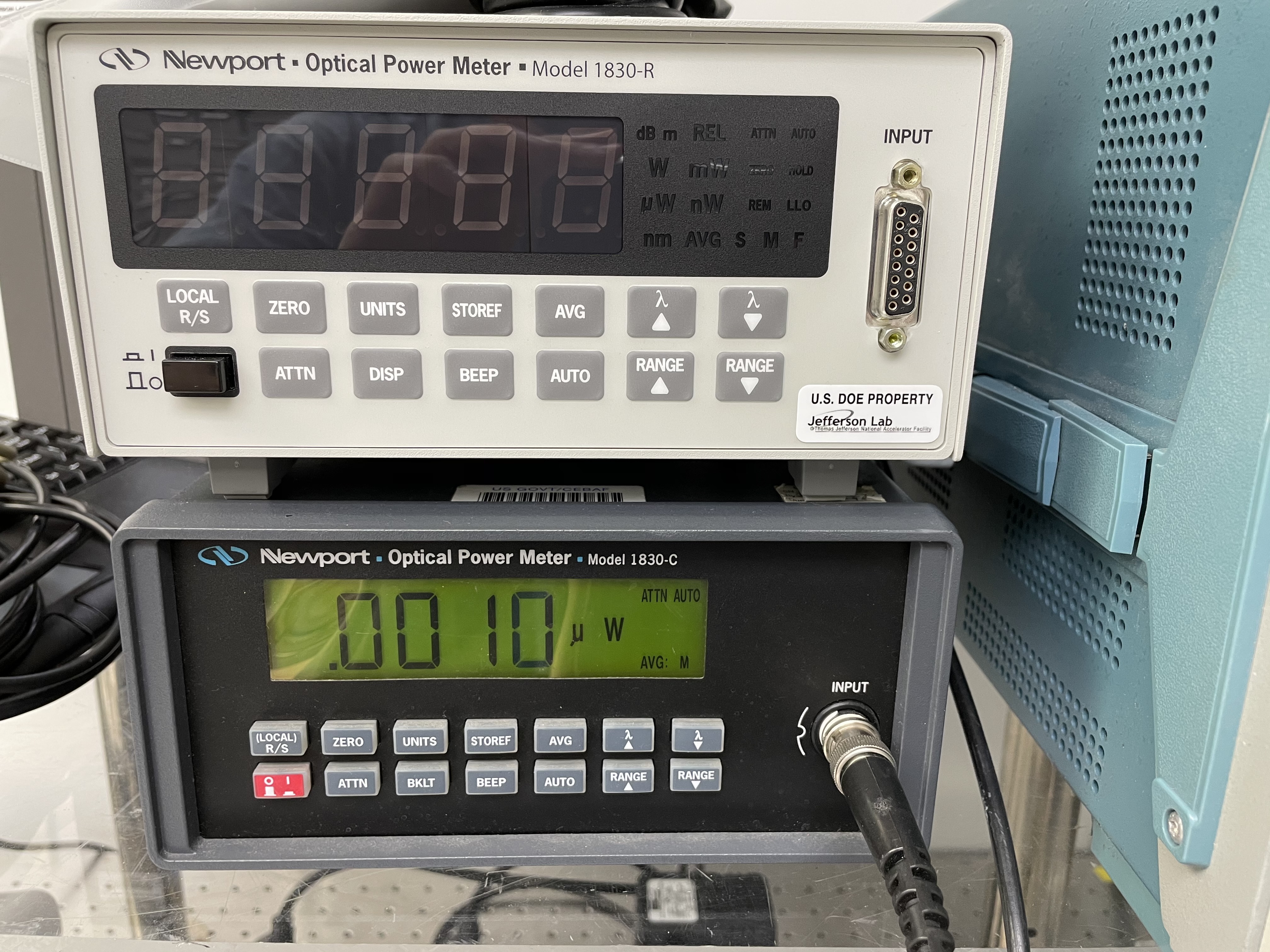
- media:IMG 7293.JPG - Newport power meter
Predicted Results
- media:Light through perpendicular window using RR rate calc.pdf - Calculations for light through perpendicular view port...should be similar to that for angled view port
Background Light Measurements
Relevant Calculations/Tech Notes/Useful Links
- List of Ghost Beam Measurements
- Go to Relevant Tech Notes
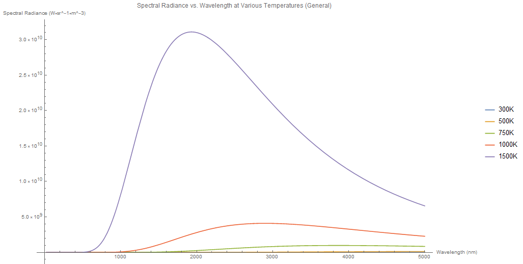
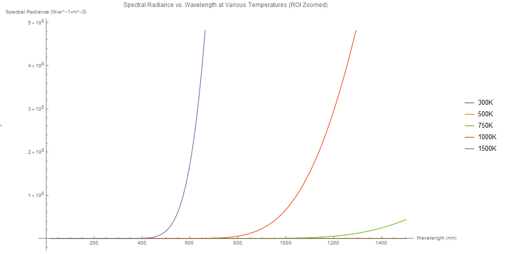
- Spectral Radiance Plots - black body spectrum vs wavelength
- media:Spectral_Radiance_vs_Wavelength_GENERAL.png - General plot over all wavelengths
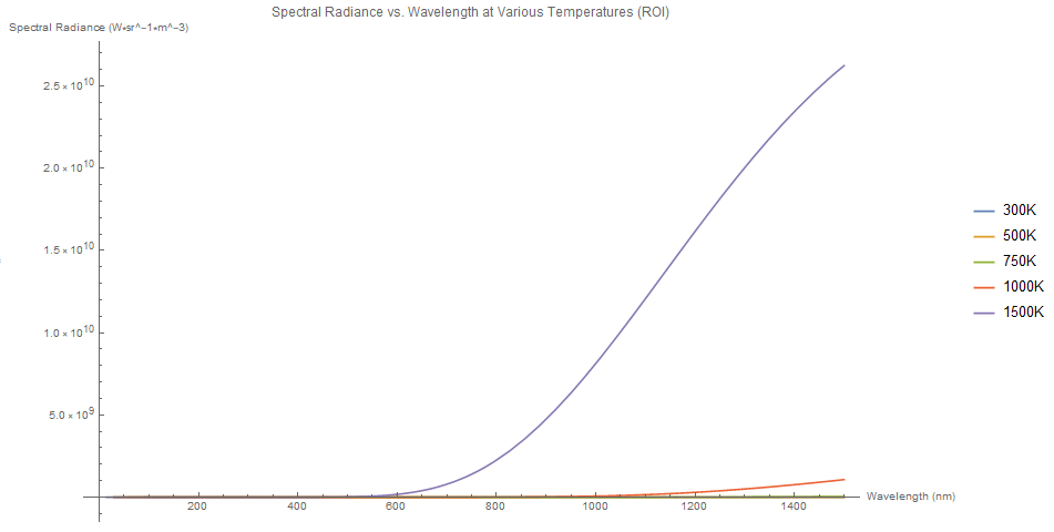
- media:Spectral_Radiance_vs_Wavelength_ROI.png - ROI for hydrogen spectral lines
- media:Spectral_Radiance_vs_Wavelength_ROI_Zoomed.png - Zoomed into ROI plot (set y-axis range to see where each temperature's spectrum rises)