Difference between revisions of "Detectors"
Jump to navigation
Jump to search


| Line 159: | Line 159: | ||
==Mott Electronics Logic Setup Procedure== | ==Mott Electronics Logic Setup Procedure== | ||
| − | Here is my | + | The above is what we did in December 2013. Here is my suggestions: |
1- Adjust HV such that signals are 200 mV. Last time we did we where shooting for about 150-200 mV. | 1- Adjust HV such that signals are 200 mV. Last time we did we where shooting for about 150-200 mV. | ||
Revision as of 17:30, 7 January 2014
Detectors
- The detectors are described in the following POLOG Entry:
http://opweb.acc.jlab.org/CSUEApps/elog02/elog_item.php?elog_id=1542515
https://cebaf.jlab.org/elog/entry/1542515
Data Sheets
- The Acrylic Light Guide is 0.125 inch x 1 inch wide x 2 inch long (data sheet: media:Light_Guide.pdf).
- The Plastic Scintillator for the DE detector is an EJ-212 machine finish of the size 1 mm x 1 inch x 1 inch
(data sheet: media:EJ-212.pdf).
- The Plastic Scintillator Rod for the E detector is an EJ-200 (data sheet: media:EJ-200.pdf) of the size
3 inch diameter x 2.5 inch long painted with EJ-510 (data sheet: media:EJ-510.pdf) with one end clear.
- The 1-inch PMT is R6427 (media:PMT_R6427.pdf) in an H7415 Assembly.
- The 3-inch PMT is R6091 (media:PMT_R6091.pdf) in an H6559 Assembly.
Logic Setup

- ΔE Detector PMT HV:
| LEFT | -1000 V |
| RIGHT | -1000 V |
| UP | -1000 V |
| DOWN | -1080 V |
- E Detector PMT HV:
| LEFT | -1125 V |
| RIGHT | -1120 V |
| UP | -1140 V |
| DOWN | -1160 V |
- ΔE Detector 792 Dual Delay Module (media:792ds.pdf):
| LEFT | 1+2+8 ns |
| RIGHT | 4+8 ns |
| UP | 0.5+4+8 ns |
| DOWN | 1+4+8 ns |
- ΔE Detector 705 Octal Discriminator Veto Thresholds (media:705ds.pdf):
| LEFT | -185 mV |
| RIGHT | -189 mV |
| UP | -185 mV |
| DOWN | -186 mV |
- ΔE Detector 715 Constant Fraction Timing Discriminator Thresholds (media:715ds.pdf):
Shaping Delay = 2 ns
| LEFT | -25 mV |
| RIGHT | -29 mV |
| UP | -27 mV |
| DOWN | -42 mV |
- E Detector 715 Constant Fraction Timing Discriminator Thresholds (media:715ds.pdf):
Shaping Delay = 4 ns
| LEFT | -25 mV |
| RIGHT | -25 mV |
| UP | -30 mV |
| DOWN | -30 mV |
Mott Electronics Logic Setup Procedure
The above is what we did in December 2013. Here is my suggestions:
1- Adjust HV such that signals are 200 mV. Last time we did we where shooting for about 150-200 mV.
2- Set E thresholds = 25 mV.
3- Set ΔE thresholds = 25 mV, we can also try 35 mV and 45 mV.
4- Set the Veto thresholds to 450 mV or 600 mV or completely remove the discriminator. Why do we need high thresholds?
Now a value of about 185 is too low and may have cut away events. Also now we can do this cut in analysis
The FADC range is 0-500 mV.
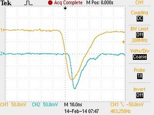
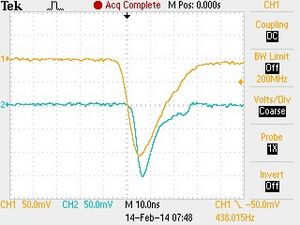
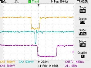
- Step 1: E and ΔE signal triggered from the E signal with a trigger threshold of -25 mV. PMT HVs are adjusted such that all signals are -200 mV.


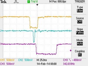
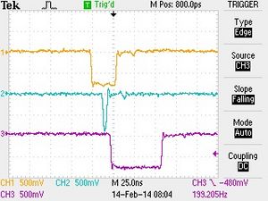
- Step 2: E trigger gate (30 ns) and ΔE trigger gate (5 ns) triggered from E signal (with ΔE delays listed above).


