Difference between revisions of "Detectors"
Jump to navigation
Jump to search


| (45 intermediate revisions by the same user not shown) | |||
| Line 1: | Line 1: | ||
| − | ==Detectors== | + | =='''Detectors'''== |
| − | * The detectors are described in the following POLOG | + | * The detectors are described in the following POLOG Entries: |
| − | |||
| − | https:// | + | https://logbooks/entry/1542515 |
| + | https://logbooks/entry/1542519 | ||
| + | https://logbooks/entry/1542529 | ||
| − | ==Data Sheets== | + | |
| + | |||
| + | =='''Data Sheets'''== | ||
- The Acrylic Light Guide is 0.125 inch x 1 inch wide x 2 inch long (data sheet: [[media:Light_Guide.pdf]]). | - The Acrylic Light Guide is 0.125 inch x 1 inch wide x 2 inch long (data sheet: [[media:Light_Guide.pdf]]). | ||
| Line 25: | Line 28: | ||
| − | ==Logic Setup== | + | =='''Old Logic Setup'''== |
[[file:Mott_Logic.jpg||600px|]] | [[file:Mott_Logic.jpg||600px|]] | ||
| + | |||
| + | [[file:TEK0377.jpg||400px|]] | ||
| Line 77: | Line 82: | ||
|- | |- | ||
| '''LEFT''' | | '''LEFT''' | ||
| − | | ''' | + | | '''0.5+4+16+32 ns''' |
|- | |- | ||
| '''RIGHT''' | | '''RIGHT''' | ||
| − | | ''' | + | | '''0.5+1+2+16+32 ns''' |
|- | |- | ||
| '''UP''' | | '''UP''' | ||
| − | | ''' | + | | '''1+2+16+32 ns ''' |
|- | |- | ||
| '''DOWN''' | | '''DOWN''' | ||
| − | | ''' | + | | '''0.5+2+16+32 ns''' |
|- | |- | ||
|} | |} | ||
| Line 152: | Line 157: | ||
| '''DOWN''' | | '''DOWN''' | ||
| '''-30 mV''' | | '''-30 mV''' | ||
| + | |- | ||
| + | |} | ||
| + | |||
| + | |||
| + | ----- | ||
| + | |||
| + | =='''New Logic Setup'''== | ||
| + | |||
| + | The above is what we had in December 2013 and earlier. On Jan 13, 2014: | ||
| + | |||
| + | 1- Adjusted HV such that signals of ΔE and E are '''-200 mV'''. FADC range = 0 to -500 mV, 0 to 2<sup>12</sup> = 4096. | ||
| + | 2- Set E thresholds = '''-25 mV'''. | ||
| + | 3- Set ΔE thresholds = '''-25 mV'''. | ||
| + | 4- Set the Veto thresholds to '''-450 mV'''. | ||
| + | |||
| + | |||
| + | |||
| + | * ΔE Detector PMT New HV: | ||
| + | |||
| + | {| class="wikitable" | ||
| + | |- | ||
| + | | '''LEFT''' | ||
| + | | '''-1300 V''' | ||
| + | |- | ||
| + | | '''RIGHT''' | ||
| + | | '''-1320 V''' | ||
| + | |- | ||
| + | | '''UP''' | ||
| + | | '''-1230 V''' | ||
| + | |- | ||
| + | | '''DOWN''' | ||
| + | | '''-1320 V''' | ||
|- | |- | ||
|} | |} | ||
| Line 157: | Line 194: | ||
| − | |||
| − | * | + | * E Detector PMT New HV: |
| + | |||
| + | {| class="wikitable" | ||
| + | |- | ||
| + | | '''LEFT''' | ||
| + | | '''-1200 V''' | ||
| + | |- | ||
| + | | '''RIGHT''' | ||
| + | | '''-1185 V''' | ||
| + | |- | ||
| + | | '''UP''' | ||
| + | | '''-1220 V''' | ||
| + | |- | ||
| + | | '''DOWN''' | ||
| + | | '''-1225 V''' | ||
| + | |- | ||
| + | |} | ||
| + | |||
| + | |||
| + | |||
| + | |||
| + | * ΔE Detector New Delays: | ||
| + | |||
| + | {| class="wikitable" | ||
| + | |- | ||
| + | | '''LEFT''' | ||
| + | | '''16+32 ns''' | ||
| + | |- | ||
| + | | '''RIGHT''' | ||
| + | | '''16+32 ns''' | ||
| + | |- | ||
| + | | '''UP''' | ||
| + | | '''16+32 ns''' | ||
| + | |- | ||
| + | | '''DOWN''' | ||
| + | | '''16+32 ns''' | ||
| + | |- | ||
| + | |} | ||
| + | |||
| + | |||
| + | |||
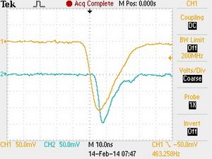
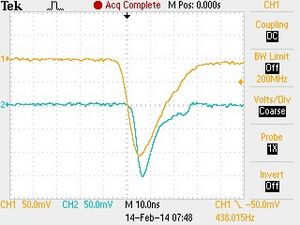
| + | * E and ΔE signal triggered from the E signal with a trigger threshold of -50 mV. PMT HVs are adjusted such that all signals are -200 mV. | ||
| + | |||
[[file:EDE_Raw_Signals_LEFT.jpg|left|300px|]] | [[file:EDE_Raw_Signals_LEFT.jpg|left|300px|]] | ||
| Line 166: | Line 244: | ||
[[file:EDE_Raw_Signals_DOWN.jpg|right|300px|]] | [[file:EDE_Raw_Signals_DOWN.jpg|right|300px|]] | ||
| + | |||
| + | [[file:ADCdEs_7298.gif||500px|]] | ||
| + | |||
| + | |||
| + | [[file:ADCEs_7298.gif||500px|]] | ||
| + | |||
| + | |||
| + | |||
| + | ----- | ||
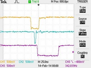
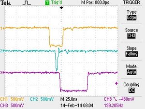
| + | * E trigger gate (30 ns) and ΔE trigger gate (5 ns) triggered from E signal (with ΔE delays listed ) and the E-ΔE Coincidence signal. | ||
| − | |||
[[file:EDE_Disc_Signals_LEFT.jpg|left|300px|]] | [[file:EDE_Disc_Signals_LEFT.jpg|left|300px|]] | ||
Latest revision as of 08:51, 25 April 2014
Detectors
- The detectors are described in the following POLOG Entries:
https://logbooks/entry/1542515
https://logbooks/entry/1542519
https://logbooks/entry/1542529
Data Sheets
- The Acrylic Light Guide is 0.125 inch x 1 inch wide x 2 inch long (data sheet: media:Light_Guide.pdf).
- The Plastic Scintillator for the DE detector is an EJ-212 machine finish of the size 1 mm x 1 inch x 1 inch
(data sheet: media:EJ-212.pdf).
- The Plastic Scintillator Rod for the E detector is an EJ-200 (data sheet: media:EJ-200.pdf) of the size
3 inch diameter x 2.5 inch long painted with EJ-510 (data sheet: media:EJ-510.pdf) with one end clear.
- The 1-inch PMT is R6427 (media:PMT_R6427.pdf) in an H7415 Assembly.
- The 3-inch PMT is R6091 (media:PMT_R6091.pdf) in an H6559 Assembly.
Old Logic Setup


- ΔE Detector PMT HV:
| LEFT | -1000 V |
| RIGHT | -1000 V |
| UP | -1000 V |
| DOWN | -1080 V |
- E Detector PMT HV:
| LEFT | -1125 V |
| RIGHT | -1120 V |
| UP | -1140 V |
| DOWN | -1160 V |
- ΔE Detector 792 Dual Delay Module (media:792ds.pdf):
| LEFT | 0.5+4+16+32 ns |
| RIGHT | 0.5+1+2+16+32 ns |
| UP | 1+2+16+32 ns |
| DOWN | 0.5+2+16+32 ns |
- ΔE Detector 705 Octal Discriminator Veto Thresholds (media:705ds.pdf):
| LEFT | -185 mV |
| RIGHT | -189 mV |
| UP | -185 mV |
| DOWN | -186 mV |
- ΔE Detector 715 Constant Fraction Timing Discriminator Thresholds (media:715ds.pdf):
Shaping Delay = 2 ns
| LEFT | -25 mV |
| RIGHT | -29 mV |
| UP | -27 mV |
| DOWN | -42 mV |
- E Detector 715 Constant Fraction Timing Discriminator Thresholds (media:715ds.pdf):
Shaping Delay = 4 ns
| LEFT | -25 mV |
| RIGHT | -25 mV |
| UP | -30 mV |
| DOWN | -30 mV |
New Logic Setup
The above is what we had in December 2013 and earlier. On Jan 13, 2014:
1- Adjusted HV such that signals of ΔE and E are -200 mV. FADC range = 0 to -500 mV, 0 to 212 = 4096.
2- Set E thresholds = -25 mV.
3- Set ΔE thresholds = -25 mV.
4- Set the Veto thresholds to -450 mV.
- ΔE Detector PMT New HV:
| LEFT | -1300 V |
| RIGHT | -1320 V |
| UP | -1230 V |
| DOWN | -1320 V |
- E Detector PMT New HV:
| LEFT | -1200 V |
| RIGHT | -1185 V |
| UP | -1220 V |
| DOWN | -1225 V |
- ΔE Detector New Delays:
| LEFT | 16+32 ns |
| RIGHT | 16+32 ns |
| UP | 16+32 ns |
| DOWN | 16+32 ns |
- E and ΔE signal triggered from the E signal with a trigger threshold of -50 mV. PMT HVs are adjusted such that all signals are -200 mV.


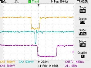
- E trigger gate (30 ns) and ΔE trigger gate (5 ns) triggered from E signal (with ΔE delays listed ) and the E-ΔE Coincidence signal.


