Detectors
Revision as of 17:31, 7 January 2014 by Suleiman (talk | contribs) (→Mott Electronics Logic Setup Procedure)
The printable version is no longer supported and may have rendering errors. Please update your browser bookmarks and please use the default browser print function instead.
Detectors
- The detectors are described in the following POLOG Entry:
http://opweb.acc.jlab.org/CSUEApps/elog02/elog_item.php?elog_id=1542515
https://cebaf.jlab.org/elog/entry/1542515
Data Sheets
- The Acrylic Light Guide is 0.125 inch x 1 inch wide x 2 inch long (data sheet: media:Light_Guide.pdf).
- The Plastic Scintillator for the DE detector is an EJ-212 machine finish of the size 1 mm x 1 inch x 1 inch
(data sheet: media:EJ-212.pdf).
- The Plastic Scintillator Rod for the E detector is an EJ-200 (data sheet: media:EJ-200.pdf) of the size
3 inch diameter x 2.5 inch long painted with EJ-510 (data sheet: media:EJ-510.pdf) with one end clear.
- The 1-inch PMT is R6427 (media:PMT_R6427.pdf) in an H7415 Assembly.
- The 3-inch PMT is R6091 (media:PMT_R6091.pdf) in an H6559 Assembly.
Logic Setup
- ΔE Detector PMT HV:
| LEFT | -1000 V |
| RIGHT | -1000 V |
| UP | -1000 V |
| DOWN | -1080 V |
- E Detector PMT HV:
| LEFT | -1125 V |
| RIGHT | -1120 V |
| UP | -1140 V |
| DOWN | -1160 V |
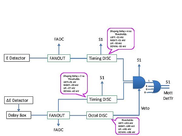
- ΔE Detector 792 Dual Delay Module (media:792ds.pdf):
| LEFT | 1+2+8 ns |
| RIGHT | 4+8 ns |
| UP | 0.5+4+8 ns |
| DOWN | 1+4+8 ns |
- ΔE Detector 705 Octal Discriminator Veto Thresholds (media:705ds.pdf):
| LEFT | -185 mV |
| RIGHT | -189 mV |
| UP | -185 mV |
| DOWN | -186 mV |
- ΔE Detector 715 Constant Fraction Timing Discriminator Thresholds (media:715ds.pdf):
Shaping Delay = 2 ns
| LEFT | -25 mV |
| RIGHT | -29 mV |
| UP | -27 mV |
| DOWN | -42 mV |
- E Detector 715 Constant Fraction Timing Discriminator Thresholds (media:715ds.pdf):
Shaping Delay = 4 ns
| LEFT | -25 mV |
| RIGHT | -25 mV |
| UP | -30 mV |
| DOWN | -30 mV |
Mott Electronics Logic Setup Procedure
The above is what we had in December 2013. Here is my suggestions:
1- Adjust HV such that signals are 200 mV. Last time we did we where shooting for about 150-200 mV.
2- Set E thresholds = 25 mV.
3- Set ΔE thresholds = 25 mV, we can also try 35 mV and 45 mV.
4- Set the Veto thresholds to 450 mV or 600 mV or completely remove the discriminator. Why do we need high thresholds?
Now a value of about 185 is too low and may have cut away events. Also now we can do this cut in analysis
The FADC range is 0-500 mV.
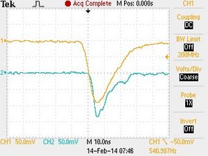
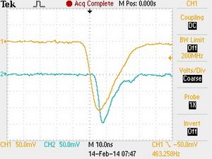
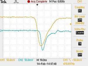
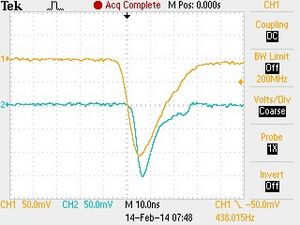
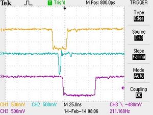
- Step 1: E and ΔE signal triggered from the E signal with a trigger threshold of -25 mV. PMT HVs are adjusted such that all signals are -200 mV.
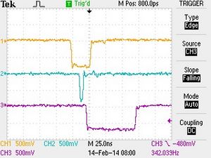
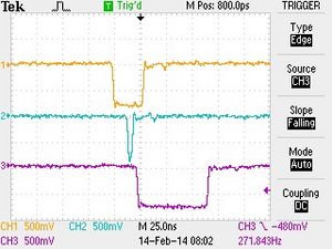
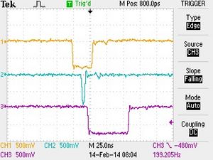
- Step 2: E trigger gate (30 ns) and ΔE trigger gate (5 ns) triggered from E signal (with ΔE delays listed above).
