Difference between revisions of "Electrode"
Jump to navigation
Jump to search
| Line 1: | Line 1: | ||
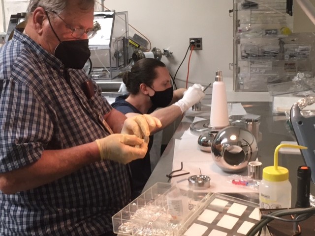
| − | * All of the electrode components are on hand and | + | * All of the electrode components are on hand and have been dry fitted by Ben Schaumloffel and Bubba Bullard in the TL1337 clean room |
| − | * Ball electrode shell, shed, from Pierce end, and back end | + | * [[File:Bubba and Ben dry fitting the electrode 03.jpg]] |
| − | * | + | * Ball electrode shell, shed, from Pierce end, and back end with holes for easier assembly have been polished |
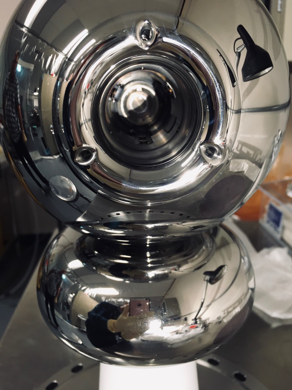
| − | + | * This is a picture of the assembled GTS electrode showing the back end with the three holes. | |
| + | * [[File:Electrode assembly on white R30 back end view zoom.jpg]] | ||
* A brand new pure alumina R30 insulator is welded to a 10" CF flange. This flange is the latest design with holes for S&A tooling, and was vacuum fired at 400 C for about 50 hours. Thee flange-ceramic assembly is stored in our HV cabinet (# 9). | * A brand new pure alumina R30 insulator is welded to a 10" CF flange. This flange is the latest design with holes for S&A tooling, and was vacuum fired at 400 C for about 50 hours. Thee flange-ceramic assembly is stored in our HV cabinet (# 9). | ||
* We should do a leak check of the ceramic assembly. | * We should do a leak check of the ceramic assembly. | ||
Latest revision as of 15:56, 28 February 2022
- All of the electrode components are on hand and have been dry fitted by Ben Schaumloffel and Bubba Bullard in the TL1337 clean room
- Ball electrode shell, shed, from Pierce end, and back end with holes for easier assembly have been polished
- This is a picture of the assembled GTS electrode showing the back end with the three holes.
- A brand new pure alumina R30 insulator is welded to a 10" CF flange. This flange is the latest design with holes for S&A tooling, and was vacuum fired at 400 C for about 50 hours. Thee flange-ceramic assembly is stored in our HV cabinet (# 9).
- We should do a leak check of the ceramic assembly.
- We should have a second pure alumina R30 insulator welded to one of the two remaining 10" CF vacuum fired flanges, as a spare set.
- The electrode needs to be put together onto the R30 pure alumina assembly.
- Use dummy puck and hand over electrode-insulator assembly to S&A
- At this point electrode assembly will be ready for installation in the 18" gun HV chamber

