Electrode
Jump to navigation
Jump to search
The printable version is no longer supported and may have rendering errors. Please update your browser bookmarks and please use the default browser print function instead.
- All of the electrode components are on hand and have been dry fitted by Ben Schaumloffel and Bubba Bullard in the TL1337 clean room
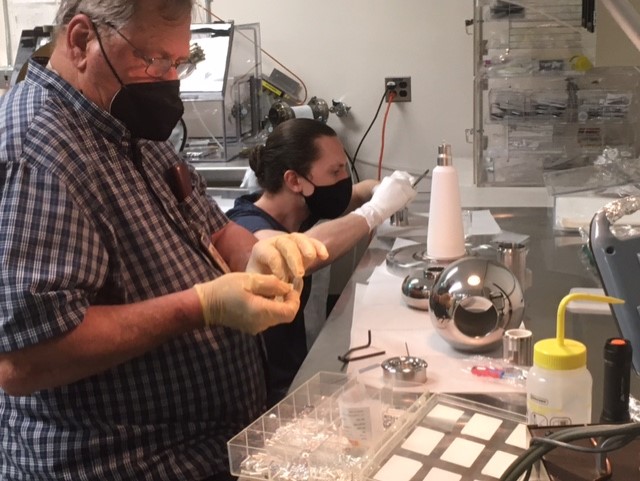
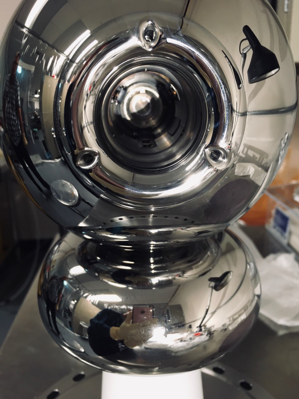
- Ball electrode shell, shed, from Pierce end, and back end with holes for easier assembly have been polished
- This is a picture of the assembled GTS electrode showing the back end with the three holes.
- A brand new pure alumina R30 insulator is welded to a 10" CF flange. This flange is the latest design with holes for S&A tooling, and was vacuum fired at 400 C for about 50 hours. Thee flange-ceramic assembly is stored in our HV cabinet (# 9).
- We should do a leak check of the ceramic assembly.
- We should have a second pure alumina R30 insulator welded to one of the two remaining 10" CF vacuum fired flanges, as a spare set.
- The electrode needs to be put together onto the R30 pure alumina assembly.
- Use dummy puck and hand over electrode-insulator assembly to S&A
- At this point electrode assembly will be ready for installation in the 18" gun HV chamber

