Glassman High Voltage Power Supplies
CEBAF 450 kV 3.0 mA

UITF 350 kV 4.5 mA

LERF 600 kV 10 mA
GTS 600 kV 5 mA
- Media:GTS Glassman HVPS Controls overview and upgrade plans.pptx
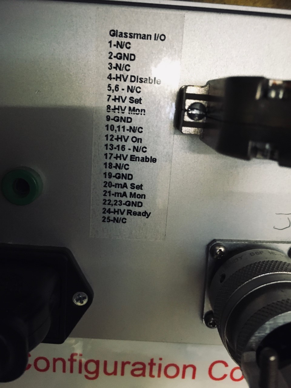
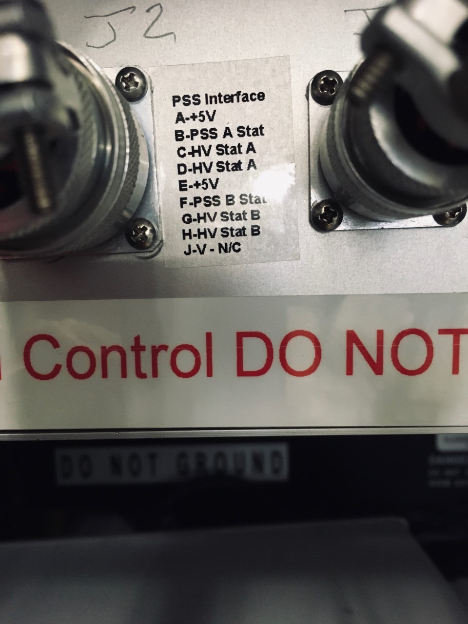
- The power supplier controller, referred to by Glassman as thee "remote unit" is an older version of the ones at UITF and CEBAF. All of them have a J1 I/O and a J2 remote interface used for the PSS. UITF and CEBAF have in addition a terminal block in the back of the controller, where the output of the interlock chassis sends the 24 VDC for enabling HV. However, the GTS controller does not have this terminal block. Instead, HV enable comes through the J1 connector once all the interlocks have been satisfied. This is what the interlock chassis did, but is is a very different interface than that in the UITF and CEBAF.
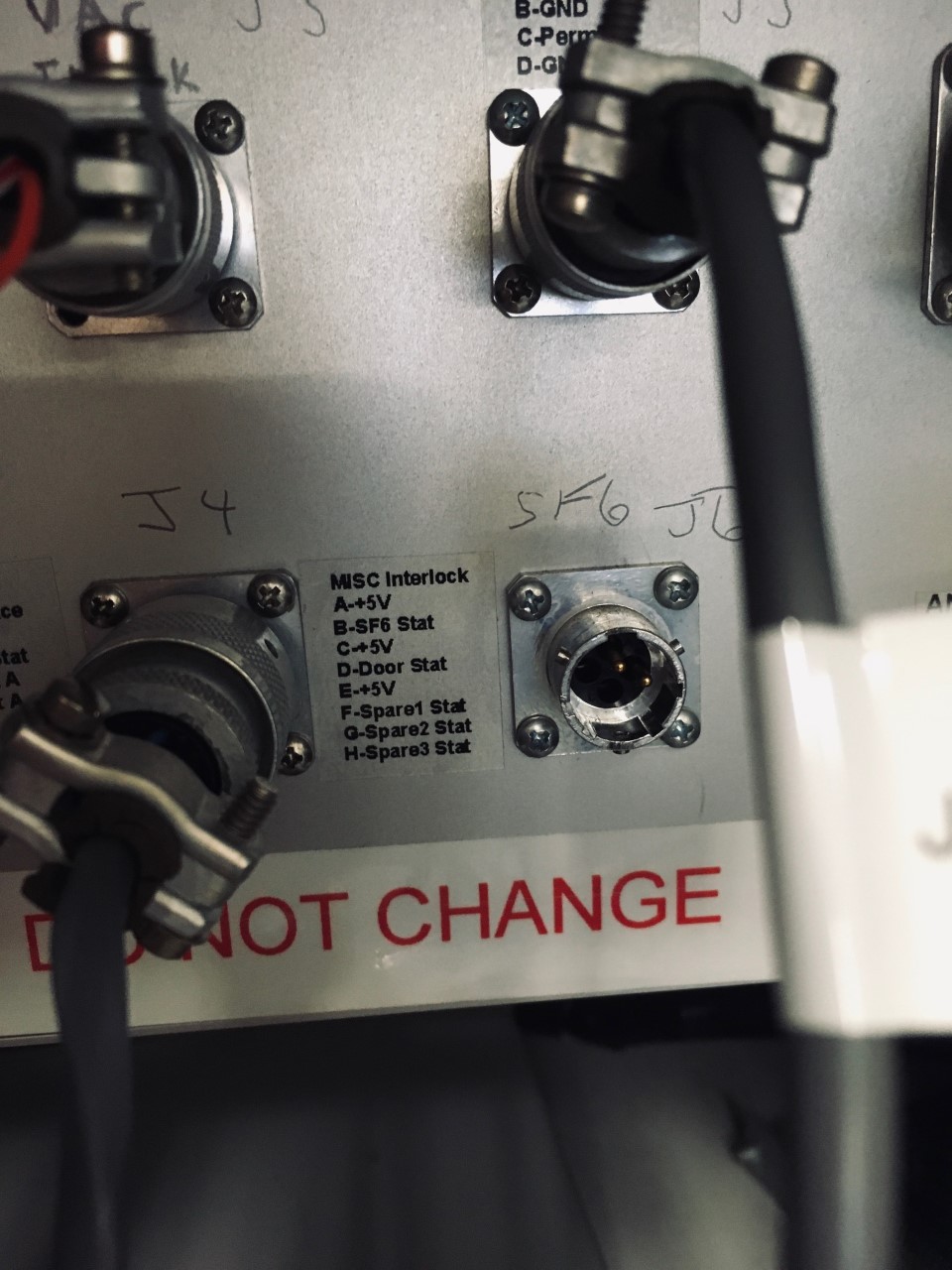
- We are trying to homogenize the GTS (and eventually the LERF) HVPS systems. Instead of fixing the on-off GTS interlock chassis, we are trying to integrate the CEBAF style interlock chassis to the old style GTS power supply controller. We need to revisit what interlock we want to have. For example, SF6 is a must, but the GTS SF6 readout is completely different from the UITF/CEBAF SF6 readout. We want to have vacuum interlock. Other interlocks that are not needed like the 15 deg dipole can be jumper out in the CEBAF style interlock chassis.
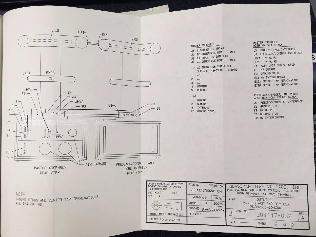
- The GTS interlock chassis and the Glassman HVPS circtui diagrams are fully documented in two folders residing (for now) in the GTS control room.
- Here are a few pictures to start us off.
- Media:Glassman HVPS driver chassis.jpg
- Media:Glassman J1 and J2 wiring.pdf
- Media:J1 connector pin call.jpg
- Media:J2 conneector pin call.jpg
- Media:J4 misc connector pin call.jpg