Difference between revisions of "P&ID best practices"
| Line 39: | Line 39: | ||
=== Connections directly from one system to another on lower-level P&Is === | === Connections directly from one system to another on lower-level P&Is === | ||
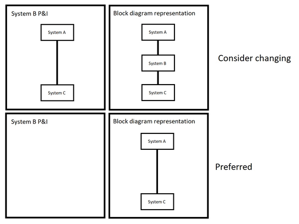
Conversely, when a line runs directly through the P&I for System B with NO piping features, this is usually bad practice. It could be shown as a direct connection between System A and System C instead. | Conversely, when a line runs directly through the P&I for System B with NO piping features, this is usually bad practice. It could be shown as a direct connection between System A and System C instead. | ||
| − | [[File:DirectConnections.png]] | + | [[File:DirectConnections.png|600px]] |
Latest revision as of 19:13, 23 September 2021
Process & Instrumentation Diagrams (P&IDs, often abbreviated "P&Is") document the general arrangement of a piping system as well as the relationships between the components that make up the piping system.
Best practices
Orient processes with respect to the TS diagram
Equipment in a thermodynamic process should be arranged on the P&I in generally the same location and orientation as they are found on a TS diagram. For example, warm compressors are shown on the P&I with the flow direction from right to left, just as they are on a TS diagram. Likewise, expansion processes are shown happening from left to right. Also, the 'main process' of the P&I will generally be oriented so the the piping with the warmest temperature located at the top of the drawing, and the coldest at the bottom.
Arrange components in a way that reflects the actual piping geometry
Piping layout and vessel shapes should loosely resemble the actual geometry, within reasonable artistic interpretation (e.g. that jog in the line may actually represent a "thermal stability loop").
More
Other "best practices" of JLab P&I development include:
- maintain no more than one vacuum enclosure per drawing
- instrument valves (e.g. isolation valves, equalization valves, bayonet purge valves, etc.) fall below the threshold of the drawing scope and are not shown
- flags (which work like GOTO statements) are used to join far-away groups of piping
- reducers are never assumed; a reducer is shown explicitly wherever there's a reducing tee
- identical, repeating components are shown once; the example cases are labeled with variables in their names
Style
JLab P&IDs were traditionally created in the ME10 drafting system. Thus, much of our "style" results from normal behavior of ME10. There are considerable limitations; for example, it's especially tough to maintain consistency between drawings.
Color
Very rarely we feel the need to create color drawings. More often we use only two or three different line thicknesses to distinguish the main process piping from the auxiliary systems.
Flags and jumps
When these lines cross, we use a "jump" to make it clear that they don't connect. It's sometimes hard to decide which line should jump the other line, but typically the auxiliary piping will give way to the main process.
Block diagrams
A block diagram is a special P&I with elevated hierarchy. Its purpose is to displays relationships between P&I blocks at a lower level of the hierarchy.
What's nice about that is that the # of relationships is very easily and quickly auditable. We can simply count the number of lines that exit the P&I for System A and enter System B, and this should match:
- On the P&I for System B: The number of lines that come from System A
- On the block diagram: The number of lines connecting A to B
Signs of architectural problems with P&I hierarchy
Tees on block diagrams
We should never see a Tee on a block diagram; teeing together related lines on the block diagram would create an error in this relationship count. Instead of representing a tee as a logical connection on a block diagram, it should be shown as a piping feature on the lower-level P&Is.
Connections directly from one system to another on lower-level P&Is
Conversely, when a line runs directly through the P&I for System B with NO piping features, this is usually bad practice. It could be shown as a direct connection between System A and System C instead.
