Difference between revisions of "Magnet"
Jump to navigation
Jump to search
| Line 19: | Line 19: | ||
* [https://wiki.jlab.org/cuawiki/images/0/01/67508-00004_S1-11_R-B_YOKE_ASSY-NPS_SWEEPER_MAGNET.pdf Production Drawings] | * [https://wiki.jlab.org/cuawiki/images/0/01/67508-00004_S1-11_R-B_YOKE_ASSY-NPS_SWEEPER_MAGNET.pdf Production Drawings] | ||
* [https://wiki.jlab.org/cuawiki/images/8/83/SAM_yoke_specifications.pdf Specifications] | * [https://wiki.jlab.org/cuawiki/images/8/83/SAM_yoke_specifications.pdf Specifications] | ||
| − | |||
== Field calculcations == | == Field calculcations == | ||
| Line 27: | Line 26: | ||
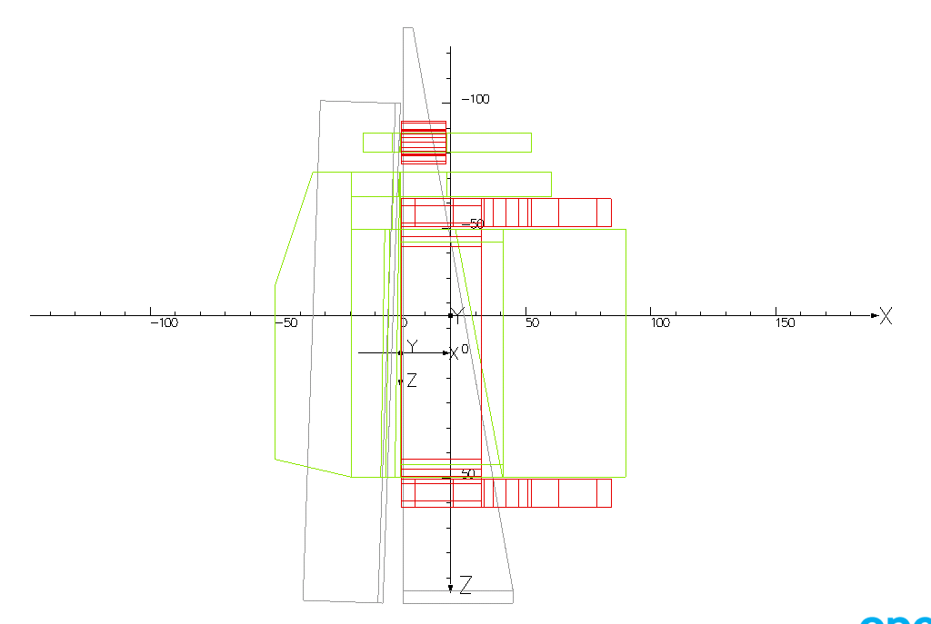
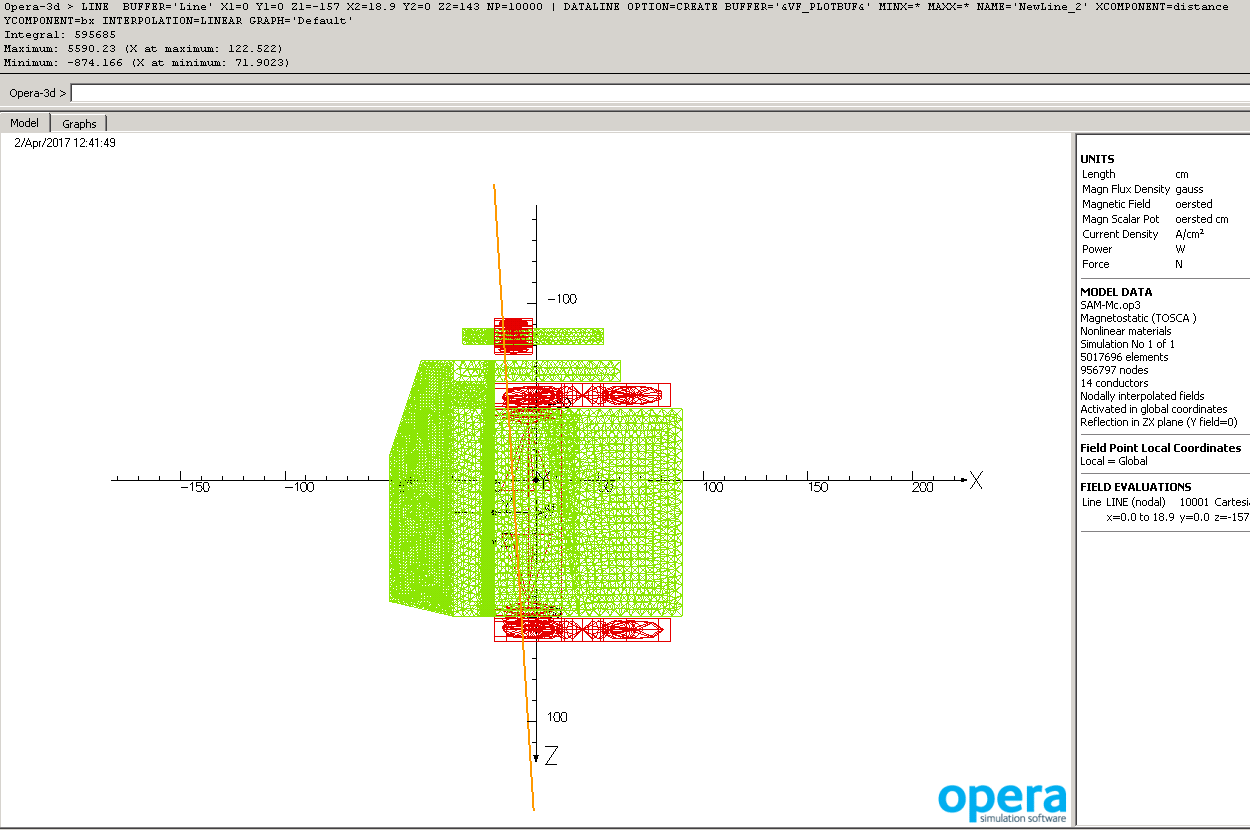
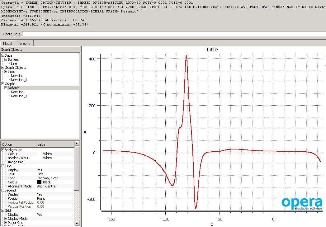
* TOSCA field results. Grid X -1cm, Y -3cm, Z -3cm. With Z=0 at 157 cm downstream of target, X=0 at small angle side of the magnet gap as shown in figure SAM_coordinates.png | * TOSCA field results. Grid X -1cm, Y -3cm, Z -3cm. With Z=0 at 157 cm downstream of target, X=0 at small angle side of the magnet gap as shown in figure SAM_coordinates.png | ||
::* [https://wiki.jlab.org/cuawiki/images/3/36/SAM_model_coordinates.png top view of the TOSCA model (along Y)] | ::* [https://wiki.jlab.org/cuawiki/images/3/36/SAM_model_coordinates.png top view of the TOSCA model (along Y)] | ||
| + | |||
| + | * [https://wiki.jlab.org/cuawiki/images/5/55/Sweeper-dimensions.pdf top view, dimensions as required for NPS experiments] | ||
* [https://wiki.jlab.org/cuawiki/images/5/5b/SAM_6.3deg.png top view for beam line] | * [https://wiki.jlab.org/cuawiki/images/5/5b/SAM_6.3deg.png top view for beam line] | ||
Revision as of 20:05, 12 April 2017
Sweeper assembly and Preparation Plan
Main Coil
Corrector Coil
Yoke
Field calculcations
- TOSCA source file
- TOSCA field results. Grid X -1cm, Y -3cm, Z -3cm. With Z=0 at 157 cm downstream of target, X=0 at small angle side of the magnet gap as shown in figure SAM_coordinates.png
Other Updates
- README instructions for using the code (Gabi)
- Compared to the original version slide #14 has been corrected: The beam deflection angle is much smaller than was shown before and also added a comment about the downstream shielding of the beam line. The original version from 30 July 2015 can be found here
- The coordinate system is based on the magnet, so the target center has the coordinates x = 15 cm, y = 0 cm, z = 157 cm. The beam going to the negative z, positive x at the angle -2.2 degree. The center of the calorimeter is in the direction +4.1 degree from the target.