Difference between revisions of "Main Page/elog:elog3"
From Gpg
Jump to navigationJump to search| (2 intermediate revisions by the same user not shown) | |||
| Line 4: | Line 4: | ||
[[File:e3f1.gif|400px|thumb|center| Fig 1. Comparison of 2.6r ALTp with radiative corrections on (blue) and off (red). ]] | [[File:e3f1.gif|400px|thumb|center| Fig 1. Comparison of 2.6r ALTp with radiative corrections on (blue) and off (red). ]] | ||
</center> | </center> | ||
| + | |||
| + | [[File:e3f1.nb]] | ||
Latest revision as of 16:51, 16 May 2011
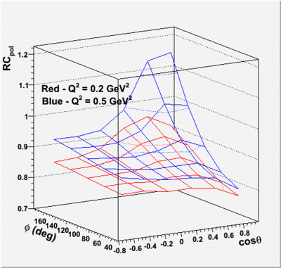
Starting collecting results for RC correction to ALTp. Since the correction appears to be significant and different and varies with phi for the polarized and unpolarized parts of the cross section, then I have to put in the correction on each separately. (1) The first step is to generate the 2D surfaces (functions of cos(theta) and phi) for polarized and unpolarized at many different Q2 values. The first plot below shows the surfaces for polarized RC correction for Q2=0.2 GeV2 (red) and Q2=0.5 GeV2 (blue). Mathematica notebooks for separate Q2 calculations are below fig 1.
