Difference between revisions of "Chiller and Temperature Sensors"
| Line 7: | Line 7: | ||
5V power supply is connected to the sensors and correct readouts are obtained. | 5V power supply is connected to the sensors and correct readouts are obtained. | ||
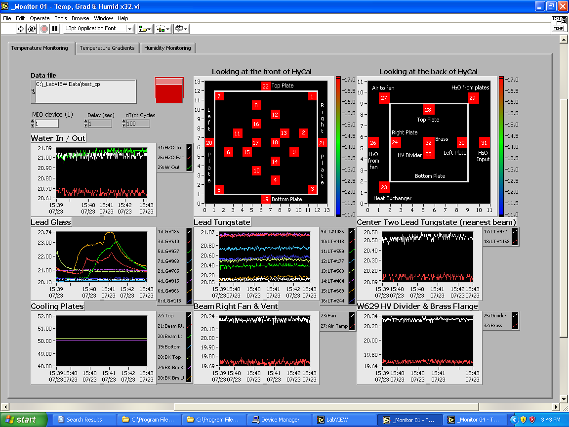
| − | The sensor 24, 28 are not working | + | The sensor 24, 28 are not working, screenshot of the program is shown below: |
| Line 14: | Line 14: | ||
Room temperature is 70 Fahrenheit (21.1 Celsius). | Room temperature is 70 Fahrenheit (21.1 Celsius). | ||
The two constant lines of 50 Ceulsius in Cooling plates panel indicate the readouts from sensor 24 and 28 are incorrect. | The two constant lines of 50 Ceulsius in Cooling plates panel indicate the readouts from sensor 24 and 28 are incorrect. | ||
| + | |||
The several peaks in Lead glass panel shows the temperature change by hand-touching. | The several peaks in Lead glass panel shows the temperature change by hand-touching. | ||
Latest revision as of 11:17, 24 July 2014
July 23, 2014
We followed the steps at http://www.jlab.org/primex/subsystems/tempmon/Hooking_Up_TempMon.txt
5V power supply is connected to the sensors and correct readouts are obtained. The sensor 24, 28 are not working, screenshot of the program is shown below:
Room temperature is 70 Fahrenheit (21.1 Celsius). The two constant lines of 50 Ceulsius in Cooling plates panel indicate the readouts from sensor 24 and 28 are incorrect.
The several peaks in Lead glass panel shows the temperature change by hand-touching.
The program we used is at C:\Program Files\National Instruments\LabVIEW 6\_DAQ VIs\2004-06 System Monitoring.llb (account primrun on the Windows machine close to the DAQ electronics)
We did not get the humidity readings from the hygrometer (Moisture Monitor
Series 3 from GE)
