02/16/16 Meeting Analysis Follow-Up
Removing Thickest Foils
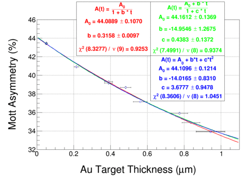
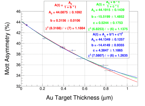
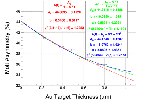
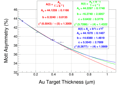
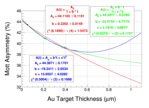
Fits of Run II data, "dilution"-subtracted, energy cut from -0.5 to +2 sigma, with thickest foils removed in sequence. Thickness data is from 1/22/16 and does not reflect newest FESEM thickness uncertainties presented 2/16/16. They, however, should not affect the fits dramatically.
Pade forms (0,1), red, former best fit; (2,0), blue, and (1,1), green are included. Note that from 2/16/16 presentation by Marty, the simulation-motivated best fit is the Pade (1,1), green on the plots, of the form
A(t) = (A0 + b * t) / (1 + c * t)
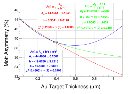 no 1000, 870, 750, 625 and 500 nm
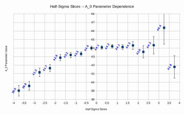
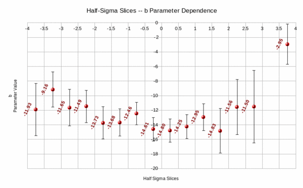
Half-Sigma Energy Slices -- Fit Parameters' Dependency
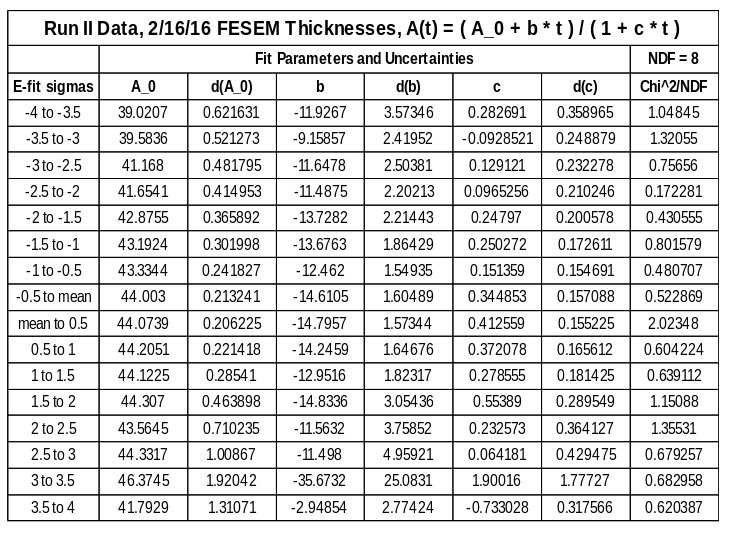
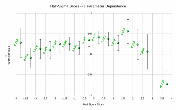
Half-sigma energy slices from -4 to +4 sigma looking at fit parameters A0, b, c from form
A(t) = (A0 + b * t) / (1 + c * t)
using Run II data and 2/16/16 FESEM thickness data. This data is not "dilution"-subtracted, as I have not done a half-sigma energy slice study for "dilution"-subtracted data from either Run.
Text Document with table media:Run2.Pade11.FitParameters.HalfSigmaSlices.odt
All data, including asymmetry by half-sigma bin for every individual foil, the above plots and data, in a spreadsheet media:Pade11.HalfSigmaSlices.AllData.ods
