|
|
| (7 intermediate revisions by the same user not shown) |
| Line 46: |
Line 46: |
| | <li>bits 24-31 the 8 bit '''Protocol Number''' (very useful for protocol decoders e.g., wireshark/tshark )</li> | | <li>bits 24-31 the 8 bit '''Protocol Number''' (very useful for protocol decoders e.g., wireshark/tshark )</li> |
| | <li>bits 32-47 or 16 bits '''Reserved, MBZ''' </li> | | <li>bits 32-47 or 16 bits '''Reserved, MBZ''' </li> |
| − | <li>bits 48-63 an unsigned 16 bit '''Entropy''' value for destination port selection</li> | + | <li>bits 48-63 an unsigned 16 bit '''Channel''' value for destination port selection</li> |
| | </ul></li> | | </ul></li> |
| | <li>'''Tick''' is an unsigned 64 bit quantity (bits 64-127) that for the duration of a data transfer session | | <li>'''Tick''' is an unsigned 64 bit quantity (bits 64-127) that for the duration of a data transfer session |
| Line 68: |
Line 68: |
| | 2 3 4 5 6 7 8 9 0 1 2 3 4 5 6 7 8 9 0 1 2 3 4 5 6 7 8 9 0 1 2 3 | | 2 3 4 5 6 7 8 9 0 1 2 3 4 5 6 7 8 9 0 1 2 3 4 5 6 7 8 9 0 1 2 3 |
| | +-+-+-+-+-+-+-+-+-+-+-+-+-+-+-+-+-+-+-+-+-+-+-+-+-+-+-+-+-+-+-+-+ | | +-+-+-+-+-+-+-+-+-+-+-+-+-+-+-+-+-+-+-+-+-+-+-+-+-+-+-+-+-+-+-+-+ |
| − | | Rsvd | Entropy | | + | | Rsvd | Channel | |
| | +-+-+-+-+-+-+-+-+-+-+-+-+-+-+-+-+-+-+-+-+-+-+-+-+-+-+-+-+-+-+-+-+ | | +-+-+-+-+-+-+-+-+-+-+-+-+-+-+-+-+-+-+-+-+-+-+-+-+-+-+-+-+-+-+-+-+ |
| | 6 12 | | 6 12 |
| Line 79: |
Line 79: |
| | </pre> | | </pre> |
| | | | |
| − | The value of the '''Tick''' field is a convention between data source and sink and '''LB control plane''' and is populated by the data source so as to send all UDP packets with a shared value to a single destination host IP; e.g., for the JLab particle detector DAQ system it would likely be timestamp. The '''Entropy''' field (bits 48-63) serves to deliver packets to a range of ports at the host IP. | + | The value of the '''Tick''' field is a convention between data source and sink and '''LB control plane''' and is populated by the data source so as to send all UDP packets with a shared value to a single destination host IP; e.g., for the JLab particle detector DAQ system it would likely be timestamp. The '''Channel''' field (bits 48-63) indicates logical channel within the data event (tick) such that channels within an event must be independently reassembled. |
| | | | |
| | == Reassembly Engine Meta-Data == | | == Reassembly Engine Meta-Data == |
| − | The '''RE meta-data''' (Figure X, yellow section) is 64 bits and consists of | + | The '''RE meta-data''' (Figure X, yellow section) is 160 bits and consists of |
| | <ul> | | <ul> |
| | <li>bits 0-3 the 4 bit ''Version'' number</li> | | <li>bits 0-3 the 4 bit ''Version'' number</li> |
| − | <li>bits 4-13 a 10 bit Reserved field</li> | + | <li>bits 4-15 a 12 bit Reserved field</li> |
| − | <li>bit 14 indicates ''first'' packet</li>
| |
| − | <li>bit 15 indicates ''last'' packet</li>
| |
| | <li>bits 16-31 an unsigned 16 bit ''Data Id''</li> | | <li>bits 16-31 an unsigned 16 bit ''Data Id''</li> |
| − | <li>bits 32-63 an unsigned 32 bit packet ''sequence number'' or optionally data ''offset'' byte number from beginning of file (BOF) for reassembly</li> | + | <li>bits 32-63 an unsigned 32 bit packet buffer ''offset'' byte number from beginning of file (BOF) for reassembly</li> |
| | + | <li>bits 64-95 an unsigned 32 bit packet buffer total byte length from beginning of file (BOF) for reassembly</li> |
| | + | <li>bits 96-159 an unsigned 64 bit tick or event number</li> |
| | </ul> | | </ul> |
| | | | |
| | In standard IETF RFC format: | | In standard IETF RFC format: |
| | | | |
| − | <pre>protocol 'Version:4,Rsvd:10,First:1,Last:1,ROC-ID:16,Offset:32' | + | <pre> |
| − | 0 1 2 3
| + | protocol 'Version:4, Rsvd:12, Data-ID:16, Offset:32, Length:32, Tick:64' |
| − | 0 1 2 3 4 5 6 7 8 9 0 1 2 3 4 5 6 7 8 9 0 1 2 3 4 5 6 7 8 9 0 1
| + | |
| − | +-+-+-+-+-+-+-+-+-+-+-+-+-+-+-+-+-+-+-+-+-+-+-+-+-+-+-+-+-+-+-+-+ | + | +-+-+-+-+-+-+-+-+-+-+-+-+-+-+-+-+-+-+-+-+-+-+-+-+-+-+-+-+-+-+-+-+-+ |
| − | |Version| Rsvd |F|L| Data-ID | | + | 0 1 2 3 |
| − | +-+-+-+-+-+-+-+-+-+-+-+-+-+-+-+-+-+-+-+-+-+-+-+-+-+-+-+-+-+-+-+-+ | + | 0 1 2 3 4 5 6 7 8 9 0 1 2 3 4 5 6 7 8 9 0 1 2 3 4 5 6 7 8 9 0 1 2 |
| − | | Packet Sequence # or Byte Offset from Beginning of File | | + | |Version | Rsvd | Data-ID | |
| − | +-+-+-+-+-+-+-+-+-+-+-+-+-+-+-+-+-+-+-+-+-+-+-+-+-+-+-+-+-+-+-+-+ | + | +-+-+-+-+-+-+-+-+-+-+-+-+-+-+-+-+-+-+-+-+-+-+-+-+-+-+-+-+-+-+-+-+-+ |
| | + | bytes 4-7 |
| | + | | Buffer Offset | |
| | + | +-+-+-+-+-+-+-+-+-+-+-+-+-+-+-+-+-+-+-+-+-+-+-+-+-+-+-+-+-+-+-+-+-+ |
| | + | bytes 8-11 |
| | + | | Buffer Length | |
| | + | +-+-+-+-+-+-+-+-+-+-+-+-+-+-+-+-+-+-+-+-+-+-+-+-+-+-+-+-+-+-+-+-+-+ |
| | + | bytes 12-19 |
| | + | | | |
| | + | + Tick + |
| | + | | | |
| | + | +-+-+-+-+-+-+-+-+-+-+-+-+-+-+-+-+-+-+-+-+-+-+-+-+-+-+-+-+-+-+-+-+-+ |
| | </pre> | | </pre> |
| | | | |
| | The '''Data Id''' field is a shared convention between data source and sink and is populated (or ignored) to suite the data transfer / load balance application, e.g., for the JLab particle detector DAQ system it would likely be ROC channel # or proxy. | | The '''Data Id''' field is a shared convention between data source and sink and is populated (or ignored) to suite the data transfer / load balance application, e.g., for the JLab particle detector DAQ system it would likely be ROC channel # or proxy. |
| | | | |
| − | The ''sequence number'' or optionally data ''offset'' byte number provides the RE with the necessary information to reassemble the transferred data into a meaningful contiguous sequence and is a shared convention between data source and sink. As such, the relationship between ''data_id'', and ''sequence number'' or ''offset'' is undefined and is application specific. In many use cases for example, the ''sequence number'' or ''offset'' will be subordinate to the ''data_id'', i.e., each set of packets with a coomon ''data_id'' will be individually sequenced as a distinct group from other groups with a different ''data_id'' for a common ''tick'' value. | + | The ''sequence number'' or optionally data ''offset'' byte number provides the RE with the necessary information to reassemble the transferred data into a meaningful contiguous sequence and is a shared convention between data source and sink. As such, the relationship between ''data_id'', and ''sequence number'' or ''offset'' is undefined and is application specific. In many use cases for example, the ''sequence number'' or ''offset'' will be subordinate to the ''data_id'', i.e., each set of packets with a common ''data_id'' will be individually sequenced as a distinct group from other groups with a different ''data_id'' for a common ''tick'' value. |
| | | | |
| | Strictly speaking, the RE meta-data is opaque to the LB and therefore considered as part of the payload and is itself therefore a convention between data producer/consumer. | | Strictly speaking, the RE meta-data is opaque to the LB and therefore considered as part of the payload and is itself therefore a convention between data producer/consumer. |
| Line 117: |
Line 128: |
| | | | |
| | = UDP Header = | | = UDP Header = |
| − | The UDP Header ''Source Port'' field can optionally be modified/populated as follows: | + | The UDP Header ''Source Port'' field '''should''' be modified/populated as follows for LAG switch entropy: |
| − | '''Source Port''' = lower 16 bits of Load Balancer '''Tick''' (for LAG switch entropy) | + | '''Source Port''' = lower 16 bits of Load Balancer '''Tick''' |
| − | The UDP Header ''Destination Port'' field '''must''' be modified/populated as follows:
| + | |
| − | '''Destination Port''' = Value that indicates LB should perform load balancing (else packet is discarded) = 'LB' = 0x4c42
| + | An example of how this can be done is available at: |
| | | | |
| | + | [https://stackoverflow.com/questions/9873061/how-to-set-the-source-port-in-the-udp-socket-in-c How to set the UDP Source Port in C] |
| | | | |
| − | The resultant data stream is shown below the block diagram and depicts the stream UDP packet structure. Individual packets | + | The UDP Header ''Destination Port'' field '''must''' be modified/populated with a value that indicates the LB should perform load balancing (else packet is discarded) as follows: |
| | + | '''Destination Port''' = 'LB' = 0x4c42 |
| | | | |
| | = Data Source Aggregation Switch = | | = Data Source Aggregation Switch = |
| Line 136: |
Line 149: |
| | | | |
| | The FPGA resident LB aggregates data across all so designated source data channels for a single discrete '''tick''' and routes this aggregated data to individual end compute nodes in cooperation with the FPGA host chassis CPU using algorithms designed for the host CPU and feedback received from the end compute node farm, maintaining complete opacity of the UDP payload to the LB (except for the LB meta-data). | | The FPGA resident LB aggregates data across all so designated source data channels for a single discrete '''tick''' and routes this aggregated data to individual end compute nodes in cooperation with the FPGA host chassis CPU using algorithms designed for the host CPU and feedback received from the end compute node farm, maintaining complete opacity of the UDP payload to the LB (except for the LB meta-data). |
| − |
| |
| − | == Data Plane (FPGA) Processing ==
| |
| − |
| |
| − | [[File:LB-data-pln.png|border|"Data Plane Flow Chart"]]
| |
| − |
| |
| − | <ul>
| |
| − | <li>Packet Parsing Stage
| |
| − | <ul>
| |
| − | <li>Headers defined in the previous stage will be parsed and made available for the remaining stages.</li>
| |
| − | <li>The Event Payload MUST NOT be parsed by the load balancer.</li>
| |
| − | </ul></li>
| |
| − | <li>Input Packet Filter Stage
| |
| − | <ul>
| |
| − | <li>Implemented as a P4 table with the following properties</li>
| |
| − | <li>Max Entries: 32</li>
| |
| − | <li>Key:
| |
| − | <ul>
| |
| − | <li>(Exact Match) EtherType</li>
| |
| − | <li>(Exact Match) (96b 0 <span class="math"> ∥ </span> IPv4 Dst) OR IPv6 Dst</li>
| |
| − | <li>(Binary Match) UDP Dst Port</li>
| |
| − | </ul></li>
| |
| − | <li>Value: None</li>
| |
| − | <li>A miss in this table MUST result in the packet being discarded since it is not intended for the load balancer.</li>
| |
| − | <li>The P4 code in this stage must also check both the Magic and Version fields in the LB Header. A mismatch from the expected values MUST result in the packet being discarded.</li>
| |
| − | </ul></li>
| |
| − | <li>Calendar Epoch Assignment Stage
| |
| − | <ul>
| |
| − | <li>Implemented as a P4 table with the following properties</li>
| |
| − | <li>Max Entries: 128</li>
| |
| − | <li>Key: (Ternary Match) 64b LB Event Number (Timestamp)</li>
| |
| − | <li>Value: 32b Calendar Epoch</li>
| |
| − | </ul></li>
| |
| − | <li>Load Balance Calendar to Member Map Stage
| |
| − | <ul>
| |
| − | <li>Implemented as a P4 table with the following properties</li>
| |
| − | <li>Max Entries: 2048</li>
| |
| − | <li>Key:
| |
| − | <ul>
| |
| − | <li>(Exact Match) 32b Calendar Epoch</li>
| |
| − | <li>(Exact Match) 9b Calendar Slot (ie. LB Event Number & 0x1FF)</li>
| |
| − | </ul></li>
| |
| − | <li>Value: 16b LB Member ID</li>
| |
| − | </ul></li>
| |
| − | <li>Load Balance Member Info Lookup Stage
| |
| − | <ul>
| |
| − | <li>Implemented as a P4 table with the following properties</li>
| |
| − | <li>Max Entries: 1K</li>
| |
| − | <li>Key:
| |
| − | <ul>
| |
| − | <li>(Exact Match) 16b EtherType (IPv4 or IPv6)</li>
| |
| − | <li>(Exact Match) 16b LB Member ID</li>
| |
| − | </ul></li>
| |
| − | <li>Value:
| |
| − | <ul>
| |
| − | <li>8b Action ID
| |
| − | <ul>
| |
| − | <li>1 = IPv4 Rewrite</li>
| |
| − | <li>2 = IPv6 Rewrite</li>
| |
| − | </ul></li>
| |
| − | <li>IPv4 Rewrite Action
| |
| − | <ul>
| |
| − | <li>48b MAC DA (for next-hop router)</li>
| |
| − | <li>32b IPv4 Dst</li>
| |
| − | <li>16b UDP Dst Port</li>
| |
| − | </ul></li>
| |
| − | <li>IPv6 Rewrite Action
| |
| − | <ul>
| |
| − | <li>48b MAC DA (for next-hop router)</li>
| |
| − | <li>128b IPv6 Dst</li>
| |
| − | <li>16b UDP Dst Port</li>
| |
| − | </ul></li>
| |
| − | </ul></li>
| |
| − | <li>'''Note:''' Rewrite Action type must match the input packet’s EtherType. E.g. An Input IPv4 packet cannot use the IPv6 Rewrite Action and vice versa.</li>
| |
| − | <li>'''Note:''' Before applying the rewrite actions, the original packet’s MAC DA should be copied into the MAC SA. This will ensure that the outgoing packet will be sent from exactly the MAC address that the original packet was destined to. This will help to keep the MAC FDB entries in the adjacent switches from expiring.</li>
| |
| − | <li>'''Note:''' Packets will be transmitted back out the port they were received on.</li>
| |
| − | </ul></li>
| |
| − | </ul>
| |
| − |
| |
| − | The resultant LB data stream is shown just above the block diagram in Figure X and depicts the stream UDP packet structure from the LB to the RE concerning an arbitrary '''single''' destination compute node. Individual packets here are still meta-data tagged both for the LB and RE. <strong>The RE for a target compute node will see a collection of packets that share a common '''tick'''</strong>.
| |
| − |
| |
| − | The depicted sequence is only illustrative, and no assumption about the order of packets with respect to the '''offset''' should be made by the RE.
| |
| − |
| |
| − | === LB Data Plane P4 Code ===
| |
| − |
| |
| − | <pre>
| |
| − | 1 // -*- Mode: c -*-
| |
| − | 2 #include <core.p4>
| |
| − | 3 #include <xsa.p4>
| |
| − |
| |
| − | 4 struct intrinsic_metadata_t {
| |
| − | 5 bit<64> ingress_global_timestamp;
| |
| − | 6 bit<64> egress_global_timestamp;
| |
| − | 7 bit<16> mcast_grp;
| |
| − | 8 bit<16> egress_rid;
| |
| − | 9 }
| |
| − |
| |
| − | 10 header ethernet_t {
| |
| − | 11 bit<48> dstAddr;
| |
| − | 12 bit<48> srcAddr;
| |
| − | 13 bit<16> etherType;
| |
| − | 14 }
| |
| − |
| |
| − | 15 header ipv6_t {
| |
| − | 16 bit<4> version;
| |
| − | 17 bit<8> trafficClass;
| |
| − | 18 bit<20> flowLabel;
| |
| − | 19 bit<16> payloadLen;
| |
| − | 20 bit<8> nextHdr;
| |
| − | 21 bit<8> hopLimit;
| |
| − | 22 bit<128> srcAddr;
| |
| − | 23 bit<128> dstAddr;
| |
| − | 24 }
| |
| − |
| |
| − | 25 header ipv4_t {
| |
| − | 26 bit<4> version;
| |
| − | 27 bit<4> ihl;
| |
| − | 28 bit<8> diffserv;
| |
| − | 29 bit<16> totalLen;
| |
| − | 30 bit<16> identification;
| |
| − | 31 bit<3> flags;
| |
| − | 32 bit<13> fragOffset;
| |
| − | 33 bit<8> ttl;
| |
| − | 34 bit<8> protocol;
| |
| − | 35 bit<16> hdrChecksum;
| |
| − | 36 bit<32> srcAddr;
| |
| − | 37 bit<32> dstAddr;
| |
| − | 38 }
| |
| − |
| |
| − | 39 header ipv4_opt_t {
| |
| − | 40 varbit<320> options; // IPv4 options - length = (ipv4.hdr_len - 5) * 32
| |
| − | 41 }
| |
| − |
| |
| − | 42 header udp_t {
| |
| − | 43 bit<16> srcPort;
| |
| − | 44 bit<16> dstPort;
| |
| − | 45 bit<16> totalLen;
| |
| − | 46 bit<16> checksum;
| |
| − | 47 }
| |
| − |
| |
| − | 48 header udplb_t {
| |
| − | 49 bit<16> magic; /* "LB" */
| |
| − | 50 bit<8> version; /* version 0 */
| |
| − | 51 bit<8> proto;
| |
| − | 52 bit<64> tick;
| |
| − | 53 }
| |
| − | 54 #define SIZEOF_UDPLB_HDR 12
| |
| − |
| |
| − | 55 struct short_metadata {
| |
| − | 56 bit<64> ingress_global_timestamp;
| |
| − | 57 bit<9> egress_spec;
| |
| − | 58 bit<1> processed;
| |
| − | 59 bit<16> packet_length;
| |
| − | 60 }
| |
| − | 61
| |
| − | 62 struct headers {
| |
| − | 63 ethernet_t ethernet;
| |
| − | 64 ipv4_t ipv4;
| |
| − | 65 ipv4_opt_t ipv4_opt;
| |
| − | 66 ipv6_t ipv6;
| |
| − | 67 udp_t udp;
| |
| − | 68 udplb_t udplb;
| |
| − | 69 }
| |
| − |
| |
| − | 70 // User-defined errors
| |
| − | 71 error {
| |
| − | 72 InvalidIPpacket,
| |
| − | 73 InvalidUDPLBmagic,
| |
| − | 74 InvalidUDPLBversion
| |
| − | 75 }
| |
| − |
| |
| − | 76 parser ParserImpl(packet_in packet, out headers hdr, inout short_metadata short_meta, inout standard_metadata_t smeta) {
| |
| − | 77 state start {
| |
| − | 78 transition parse_ethernet;
| |
| − | 79 }
| |
| − |
| |
| − | 80 state parse_ethernet {
| |
| − | 81 packet.extract(hdr.ethernet);
| |
| − | 82 transition select(hdr.ethernet.etherType) {
| |
| − | 83 16w0x0800: parse_ipv4;
| |
| − | 84 16w0x86dd: parse_ipv6;
| |
| − | 85 default: accept;
| |
| − | 86 }
| |
| − | 87 }
| |
| − | 88 state parse_ipv4 {
| |
| − | 89 packet.extract(hdr.ipv4);
| |
| − | 90 verify(hdr.ipv4.version == 4 && hdr.ipv4.ihl >= 5, error.InvalidIPpacket);
| |
| − | 91 packet.extract(hdr.ipv4_opt, (((bit<32>)hdr.ipv4.ihl - 5) * 32));
| |
| − | 92 transition select(hdr.ipv4.protocol) {
| |
| − | 93 8w17: parse_udp;
| |
| − | 94 default: accept;
| |
| − | 95 }
| |
| − | 96 }
| |
| − | 97 state parse_ipv6 {
| |
| − | 98 packet.extract(hdr.ipv6);
| |
| − | 99 verify(hdr.ipv6.version == 6, error.InvalidIPpacket);
| |
| − | 100 transition select(hdr.ipv6.nextHdr) {
| |
| − | 101 8w17: parse_udp;
| |
| − | 102 default: accept;
| |
| − | 103 }
| |
| − | 104 }
| |
| − | 105 state parse_udp {
| |
| − | 106 packet.extract(hdr.udp);
| |
| − | 107 transition select(hdr.udp.dstPort) {
| |
| − | 108 16w0x4c42: parse_udplb;
| |
| − | 109 default: accept;
| |
| − | 110 }
| |
| − | 111 }
| |
| − |
| |
| − | 112 state parse_udplb {
| |
| − | 113 packet.extract(hdr.udplb);
| |
| − | 114 verify(hdr.udplb.magic == 0x4c42, error.InvalidUDPLBmagic);
| |
| − | 115 verify(hdr.udplb.version == 1, error.InvalidUDPLBversion);
| |
| − | 116 transition accept;
| |
| − | 117 }
| |
| − | 118 }
| |
| − |
| |
| − | 119 control MatchActionImpl(inout headers hdr, inout short_metadata short_meta, inout standard_metadata_t smeta) {
| |
| − |
| |
| − | 120 //
| |
| − | 121 // DstFilter - a gate
| |
| − | 122 //
| |
| − |
| |
| − | 123 bit<128> meta_ipdst = 128w0;
| |
| − | 124
| |
| − | 125 action drop() {
| |
| − | 126 smeta.drop = 1;
| |
| − | 127 }
| |
| − | 128
| |
| − | 129 table dst_filter_table { // layer 2/3 filter
| |
| − | 130 actions = {
| |
| − | 131 drop;
| |
| − | 132 NoAction;
| |
| − | 133 }
| |
| − | 134 key = {
| |
| − | 135 hdr.ethernet.dstAddr : exact; // this a unicast packet for us at layer 2 (MAC) ?
| |
| − | 136 hdr.ethernet.etherType : exact // ipv4 or ipv6
| |
| − | 137 meta_ipdst : exact; // normalized 128b IP (not MAC) address from either ipv4/6
| |
| − | 138 }
| |
| − | 139 size = 32;
| |
| − | 140 default_action = drop;
| |
| − | 141 }
| |
| − |
| |
| − | 142 //
| |
| − | 143 // EpochAssign
| |
| − | 144 //
| |
| − |
| |
| − | 145 bit<32> meta_epoch = 0;
| |
| − | 146
| |
| − | 147 action do_assign_epoch(bit<32> epoch) {
| |
| − | 148 meta_epoch = epoch;
| |
| − | 149 }
| |
| − |
| |
| − | 150 table epoch_assign_table {
| |
| − | 151 actions = {
| |
| − | 152 do_assign_epoch;
| |
| − | 153 drop;
| |
| − | 154 }
| |
| − | 155 key = {
| |
| − | 156 hdr.udplb.tick : lpm; // lpm is the keystone to routing everywhere
| |
| − | 157 }
| |
| − | 158 size = 128;
| |
| − | 159 default_action = drop;
| |
| − | 160 }
| |
| − |
| |
| − | 161 //
| |
| − | 162 // LoadBalanceCalendar
| |
| − | 163 //
| |
| − |
| |
| − | 164 // Use lsbs of tick to select a calendar slot
| |
| − | 165 bit<9> calendar_slot = (bit<9>) hdr.udplb.tick & 0x1FF; # 9 bits
| |
| − | 166 bit<16> meta_member_id = 0;
| |
| − |
| |
| − | 167 action do_assign_member(bit<16> member_id) {
| |
| − | 168 meta_member_id = member_id;
| |
| − | 169 }
| |
| − |
| |
| − | 170 table load_balance_calendar_table {
| |
| − | 171 actions = {
| |
| − | 172 do_assign_member;
| |
| − | 173 drop;
| |
| − | 174 }
| |
| − | 175 key = {
| |
| − | 176 meta_epoch : exact;
| |
| − | 177 calendar_slot : exact;
| |
| − | 178 }
| |
| − | 179 size = 2048;
| |
| − | 180 default_action = drop;
| |
| − | 181 }
| |
| − | 182
| |
| − | 183 //
| |
| − | 184 // MemberInfoLookup
| |
| − | 185 //
| |
| − |
| |
| − | 186 // Cumulative checksum delta due to field rewrites
| |
| − | 187 bit<16> ckd = 0;
| |
| − | 188 bit<16> new_udp_dst = 0;
| |
| − |
| |
| − | 189 action cksum_sub(inout bit<16> cksum, in bit<16> a) {
| |
| − | 190 bit<17> sum = (bit<17>) cksum;
| |
| − |
| |
| − | 191 sum = sum + (bit<17>)(a ^ 0xFFFF);
| |
| − | 192 sum = (sum & 0xFFFF) + (sum >> 16);
| |
| − |
| |
| − | 193 cksum = sum[15:0];
| |
| − | 194 }
| |
| − |
| |
| − | 195 action cksum_add(inout bit<16> cksum, in bit<16> a) {
| |
| − | 196 bit<17> sum = (bit<17>) cksum;
| |
| − |
| |
| − | 197 sum = sum + (bit<17>)a;
| |
| − | 198 sum = (sum & 0xFFFF) + (sum >> 16);
| |
| − |
| |
| − | 199 cksum = sum[15:0];
| |
| − | 200 }
| |
| − |
| |
| − | 201 action cksum_swap(inout bit<16> cksum, in bit<16> old, in bit<16> new) {
| |
| − | 202 cksum_sub(cksum, old);
| |
| − | 203 cksum_add(cksum, new);
| |
| − | 204 }
| |
| − |
| |
| − | 205 action do_ipv4_member_rewrite(bit<48> mac_dst, bit<32> ip_dst, bit<16> udp_dst) {
| |
| − | 206 // Calculate IPv4 and UDP pseudo header checksum delta using rfc1624 method
| |
| − |
| |
| − | 207 cksum_swap(ckd, hdr.ipv4.dstAddr[31:16], ip_dst[31:16]);
| |
| − | 208 cksum_swap(ckd, hdr.ipv4.dstAddr[15:00], ip_dst[15:00]);
| |
| − | 209 cksum_swap(ckd, hdr.ipv4.totalLen, hdr.ipv4.totalLen - SIZEOF_UDPLB_HDR);
| |
| − |
| |
| − | 210 // Apply the accumulated delta to the IPv4 header checksum
| |
| − | 211 hdr.ipv4.hdrChecksum = hdr.ipv4.hdrChecksum ^ 0xFFFF;
| |
| − | 212 cksum_add(hdr.ipv4.hdrChecksum, ckd);
| |
| − | 213 hdr.ipv4.hdrChecksum = hdr.ipv4.hdrChecksum ^ 0xFFFF;
| |
| − |
| |
| − | 214 hdr.ethernet.dstAddr = mac_dst;
| |
| − | 215 hdr.ipv4.dstAddr = ip_dst;
| |
| − | 216 hdr.ipv4.totalLen = hdr.ipv4.totalLen - SIZEOF_UDPLB_HDR;
| |
| − |
| |
| − | 217 new_udp_dst = udp_dst;
| |
| − | 218 }
| |
| − |
| |
| − | 219 action do_ipv6_member_rewrite(bit<48> mac_dst, bit<128> ip_dst, bit<16> udp_dst) {
| |
| − | 220 // Calculate UDP pseudo header checksum delta using rfc1624 method
| |
| − |
| |
| − | 221 cksum_swap(ckd, hdr.ipv6.dstAddr[63:48], ip_dst[63:48]);
| |
| − | 222 cksum_swap(ckd, hdr.ipv6.dstAddr[47:32], ip_dst[47:32]);
| |
| − | 223 cksum_swap(ckd, hdr.ipv6.dstAddr[31:16], ip_dst[31:16]);
| |
| − | 224 cksum_swap(ckd, hdr.ipv6.dstAddr[15:00], ip_dst[15:00]);
| |
| − |
| |
| − | 225 cksum_swap(ckd, hdr.ipv6.payloadLen, hdr.ipv6.payloadLen - SIZEOF_UDPLB_HDR);
| |
| − |
| |
| − | 226 hdr.ethernet.dstAddr = mac_dst;
| |
| − | 227 hdr.ipv6.dstAddr = ip_dst;
| |
| − | 228 hdr.ipv6.payloadLen = hdr.ipv6.payloadLen - 12;
| |
| − | 229 new_udp_dst = udp_dst;
| |
| − | 230 }
| |
| − |
| |
| − | 231 table member_info_lookup_table {
| |
| − | 232 actions = {
| |
| − | 233 do_ipv4_member_rewrite;
| |
| − | 234 do_ipv6_member_rewrite;
| |
| − | 235 drop;
| |
| − | 236 }
| |
| − | 237 key = {
| |
| − | 238 hdr.ethernet.etherType : exact;
| |
| − | 239 meta_member_id : exact;
| |
| − | 240 }
| |
| − | 241 size = 1024;
| |
| − | 242 default_action = drop;
| |
| − | 243 }
| |
| − |
| |
| − | 244 // Entry Point
| |
| − | 245 apply {
| |
| − | 246 bool hit;
| |
| − |
| |
| − | 247 //
| |
| − | 248 // DstFilter
| |
| − | 249 //
| |
| − | 250
| |
| − | 251 // Normalized IP destination address for both ipv4 and ipv6
| |
| − | 252 if (hdr.ipv4.isValid()) {
| |
| − | 253 meta_ipdst = (bit<96>) 0 ++ (bit<32>) hdr.ipv4.dstAddr;
| |
| − | 254 } else if (hdr.ipv6.isValid()) {
| |
| − | 255 meta_ipdst = hdr.ipv6.dstAddr;
| |
| − | 256 }
| |
| − | 257
| |
| − | 258 // .apply() looks up key and applies action specified by control plane on match
| |
| − | 259 hit = dst_filter_table.apply().hit;
| |
| − | 260 if (!hit) {
| |
| − | 261 return;
| |
| − | 262 }
| |
| − |
| |
| − | 263 //
| |
| − | 264 // EpochAssign
| |
| − | 265 //
| |
| − |
| |
| − | 266 if (!hdr.udplb.isValid()) {
| |
| − | 267 return;
| |
| − | 268 }
| |
| − |
| |
| − | 269 hit = epoch_assign_table.apply().hit;
| |
| − | 270 if (!hit) {
| |
| − | 271 return;
| |
| − | 272 }
| |
| − |
| |
| − | 273 //
| |
| − | 274 // LoadBalanceCalendar
| |
| − | 275 //
| |
| − |
| |
| − | 276 hit = load_balance_calendar_table.apply().hit;
| |
| − | 277 if (!hit) {
| |
| − | 278 return;
| |
| − | 279 }
| |
| − |
| |
| − | 280 //
| |
| − | 281 // MemberInfoLookup
| |
| − | 282 //
| |
| − |
| |
| − | 283 hit = member_info_lookup_table.apply().hit;
| |
| − | 284 if (!hit) {
| |
| − | 285 return;
| |
| − | 286 }
| |
| − |
| |
| − | 287 //
| |
| − | 288 // UpdateUDPChecksum
| |
| − | 289 //
| |
| − |
| |
| − | 290 // Calculate UDP pseudo header checksum delta using rfc1624 method
| |
| − |
| |
| − | 291 cksum_swap(ckd, hdr.udp.dstPort, new_udp_dst);
| |
| − | 292 cksum_swap(ckd, hdr.udp.totalLen, hdr.udp.totalLen - SIZEOF_UDPLB_HDR);
| |
| − |
| |
| − | 293 // Subtract out the bytes of the UDP load-balance header
| |
| − | 294 cksum_sub(ckd, hdr.udplb.magic);
| |
| − | 295 cksum_sub(ckd, hdr.udplb.version ++ hdr.udplb.proto);
| |
| − | 296 cksum_sub(ckd, hdr.udplb.tick[63:48]);
| |
| − | 297 cksum_sub(ckd, hdr.udplb.tick[47:32]);
| |
| − | 298 cksum_sub(ckd, hdr.udplb.tick[31:16]);
| |
| − | 299 cksum_sub(ckd, hdr.udplb.tick[15:00]);
| |
| − |
| |
| − | 300 // Write the updated checksum back into the packet
| |
| − | 301 hdr.udp.checksum = hdr.udp.checksum ^ 0xFFFF;
| |
| − | 302 cksum_add(hdr.udp.checksum, ckd);
| |
| − | 303 hdr.udp.checksum = hdr.udp.checksum ^ 0xFFFF;
| |
| − |
| |
| − | 304 // Update destination port and fix up length to adapt to dropped udplb header
| |
| − | 305 hdr.udp.dstPort = new_udp_dst;
| |
| − | 306 hdr.udp.totalLen = hdr.udp.totalLen - SIZEOF_UDPLB_HDR;
| |
| − | 307 }
| |
| − | 308 }
| |
| − |
| |
| − | 309 control DeparserImpl(packet_out packet, in headers hdr, inout short_metadata short_meta, inout standard_metadata_t smeta) {
| |
| − | 310 apply {
| |
| − | 311 packet.emit(hdr.ethernet);
| |
| − | 312 packet.emit(hdr.ipv4);
| |
| − | 313 packet.emit(hdr.ipv4_opt);
| |
| − | 314 packet.emit(hdr.ipv6);
| |
| − | 315 packet.emit(hdr.udp);
| |
| − | 316 }
| |
| − | 317 }
| |
| − |
| |
| − | 318 XilinxPipeline(
| |
| − | 319 ParserImpl(),
| |
| − | 320 MatchActionImpl(),
| |
| − | 321 DeparserImpl()
| |
| − | 322 ) main;
| |
| − |
| |
| − | </pre>
| |
| − |
| |
| − | ==== Notes: ====
| |
| − |
| |
| − | <ul>
| |
| − | <li>lines 11-12: These are MAC addresses</li>
| |
| − | <li>line 40: IPV4 options length = (ipv4 <span class="math"> × </span> hdrlen - 5) <span class="math"> × </span> 32</li>
| |
| − | <li>line 49: literally “LB” = 0x4c42; c.f. section [sec:Load Balancer Meta-Data] and line 8 section [sec:rocpcap].</li>
| |
| − | <li>line 50: LB version; c.f. line 9 section [sec:rocpcap]</li>
| |
| − | <li>line 51: protocol; c.f. line 10 section [sec:rocpcap], section [sec:roc]</li>
| |
| − | <li>line 135, 259: Gate to ensure in packet is for LB</li>
| |
| − | <li>line 156: '''epoch''' is determined by '''largest''' prefix match of '''tick'''; c.f. section X lines 18,25 for epochs 0,1 respectively</li>
| |
| − | <li>line 165: lower 9 bits of '''tick''' used for member slot indexing on round-robin basis; all 512 member slots require population for all '''active''' epochs; c.f. line 33 section [sec:lbcntrlpln]</li>
| |
| − | </ul>
| |
| − |
| |
| − | == Control Plane (Host CPU) Processing ==
| |
| − |
| |
| − |
| |
| − | <ul>
| |
| − | <li>Software Initialization Steps
| |
| − | <ul>
| |
| − | <li>PROPOSAL: A low-level C Software library will be provided to allow insertion/deletion of table entries into each of the P4 tables. All other SW will likely need to be written by the user of the LB pipeline.</li>
| |
| − | <li>Populate Input Packet Filter Table
| |
| − | <ul>
| |
| − | <li>Table Insert <span class="math">⟨</span>0x800, LB IPv4 Addr, LB UDP Dst<span class="math">⟩</span></li>
| |
| − | <li>Table Insert <span class="math">⟨</span>0x86dd, LB IPv6 Addr, LB UDP Dst<span class="math">⟩</span></li>
| |
| − | </ul></li>
| |
| − | <li>Populate Load Balance Member Table: For each LB Member
| |
| − | <ul>
| |
| − | <li>Allocate next free Member ID number from SW pool</li>
| |
| − | <li>Table Insert
| |
| − | <ul>
| |
| − | <li>K: <span class="math">⟨</span>0x800, Member ID<span class="math">⟩</span></li>
| |
| − | <li>V: <span class="math">⟨</span>IPv4 Rewrite, 0, Next-Hop MAC DA, Worker IPv4 Dst, Worker UDP Dst Port<span class="math">⟩</span></li>
| |
| − | </ul></li>
| |
| − | <li>Table Insert
| |
| − | <ul>
| |
| − | <li>K: <span class="math">⟨</span>0x86dd, Member ID<span class="math">⟩</span></li>
| |
| − | <li>V: <span class="math">⟨</span>IPv6 Rewrite, 0, Next-Hop MAC DA, Worker IPv6 Dst, Worker UDP Dst Port<span class="math">⟩</span></li>
| |
| − | </ul></li>
| |
| − | </ul></li>
| |
| − | <li>Populate Load Balance to Member Map Table
| |
| − | <ul>
| |
| − | <li>Allocate next free Calendar Epoch number from SW pool</li>
| |
| − | <li>Assign all active LB Member IDs to the 512 Calendar Slots
| |
| − | <ul>
| |
| − | <li>Any members can occur between 0-512 times in the calendar</li>
| |
| − | <li>A member occurring more times in the calendar has a higher “weight” and will be more likely to be assigned an event within this Calendar Epoch</li>
| |
| − | <li>All 512 slots MUST have a member assigned to them or events that target the empty slot will be entirely discarded by the load balancer</li>
| |
| − | </ul></li>
| |
| − | <li>For each Calendar Slot Table Insert
| |
| − | <ul>
| |
| − | <li>K: <span class="math">⟨</span>Calendar Epoch, Calendar Slot<span class="math">⟩</span></li>
| |
| − | <li>V: <span class="math">⟨</span>LB Member ID<span class="math">⟩</span></li>
| |
| − | </ul></li>
| |
| − | </ul></li>
| |
| − | <li>Populate the Calendar Epoch Assignment Table
| |
| − | <ul>
| |
| − | <li>Assign all Event IDs (Timestamps) to the newly allocated Calendar Epoch</li>
| |
| − | <li>Table Insert
| |
| − | <ul>
| |
| − | <li>K: <span class="math">⟨</span>*<span class="math">⟩</span></li>
| |
| − | <li>V: <span class="math">⟨</span>Calendar Epoch<span class="math">⟩</span></li>
| |
| − | </ul></li>
| |
| − | </ul></li>
| |
| − | <li>The load balancer will now assign each Rx’d packet to exactly one of the LB members based on the Event ID contained in the packet. The mapping will remain consistent for any given Event ID within an Epoch since the Calendar and Member tables cannot change within a given Epoch.</li>
| |
| − | </ul></li>
| |
| − | <li>Making Changes to the Load Balancer ConfigurationThis section assumes that the load balancer is in-service and as such, care must be taken to avoid service disruption during reconfiguration. If the load balancer is out-of-service, you can reconfigure it using the Initialization steps above without care for disruption.
| |
| − | Any Epoch that is reachable (connected) via the Calendar Epoch Assignment table MUST not be changed. In-service reconfiguration of the load balancer is done by the following steps.
| |
| − | <ul>
| |
| − | <li>Allocate the next free Calendar Epoch ID: Once we’re done all the rest of the updates, we’ll activate this new Epoch</li>
| |
| − | <li>Insert new entries into the Load Balance Member Table for any entries that need to be different in the next Epoch</li>
| |
| − | <li>Compute and insert an entirely new calendar into the Load Balance to Member Map Table using the next Calendar Epoch ID</li>
| |
| − | <li>Choose an Event ID in the (near) future which will become the boundary between the current Epoch and the new Epoch.</li>
| |
| − | <li>Compute a set of Ternary prefix matches over the Event ID space which describe the entire range of Event IDs from the start of the current Epoch up to the start of the new Epoch.</li>
| |
| − | <li>Program the ternary prefix matches into the Calendar Epoch Assignment Table</li>
| |
| − | <li>Update the wildcard match in the Calendar Epoch Assignment Table to point to the new Epoch</li>
| |
| − | </ul></li>
| |
| − | <li>The new Epoch is activated and MUST NOT be changed</li>
| |
| − | <li>After waiting an appropriate time for all events from the previous Epoch to have quiesced, perform the following cleanup steps.
| |
| − | <ul>
| |
| − | <li>Delete the ternary prefix matches for the previous Epoch from the Calendar Epoch Assignment Table. This disconnects all references for the previous Epoch to the rest of the pipeline tables.</li>
| |
| − | <li>Delete the Calendar for the previous Epoch</li>
| |
| − | <li>Delete the Member rewrites for the previous Calendar</li>
| |
| − | </ul></li>
| |
| − | </ul>
| |
| − |
| |
| − | === Control Plane Flowchart ===
| |
| − |
| |
| − | [[File:LB-cntrl-pln.png|border|"Control Plane Flow Chart"]]
| |
| − |
| |
| − | === Example Control Plane CLI configuration script ===
| |
| − |
| |
| − | <pre>
| |
| − | 1 table_add
| |
| − | 2 dst_filter_table
| |
| − | 3 NoAction
| |
| − | 4 0x00aabbccddee # set FPGA MAC = 00.170.187.204.221.238
| |
| − | 5 0x0800 # ipv4
| |
| − | 6 0x0000000000000000000000000a010203 # set FPGA IPV4 meta_ipdst = 10.1.2.3
| |
| − | 7 =>
| |
| − | 8 table_add
| |
| − | 9 dst_filter_table
| |
| − | 10 NoAction
| |
| − | 11 0x00aabbccddee # set FPGA MAC = 00.170.187.204.221.238
| |
| − | 12 0x86dd # ipv6
| |
| − | 13 0xfe800000000000000000000000000002 # set FPGA IPV6 meta_ipdst = 254.128.00.0 ?? 0.3
| |
| − | 14 =>
| |
| − | 15 table_add
| |
| − | 16 epoch_assign_table
| |
| − | 17 do_assign_epoch
| |
| − | 18 0x0000000000000000/0 # tick/lpm (match high 0b); all ticks = epoch 0
| |
| − | 19 =>
| |
| − | 20 0x00000000 # epoch
| |
| − | 21 64 # priority (low is higher)
| |
| − | 22 table_add
| |
| − | 23 epoch_assign_table
| |
| − | 24 do_assign_epoch
| |
| − | 25 0x0000000000000010/60 # tick/lpm (match high 60b); 16 ticks = epoch 1
| |
| − | 26 =>
| |
| − | 27 0x00000001 # epoch
| |
| − | 28 5 # priority (low is higher)
| |
| − | 29 table_add
| |
| − | 30 load_balance_calendar_table
| |
| − | 31 do_assign_member
| |
| − | 32 0x00000000 # meta_epoch
| |
| − | 33 0x00a # calendar_slot or tick lsb ; 0x00a = 10; see line #42 ROC PCAP Generator Script
| |
| − | 34 =>
| |
| − | 35 0x0000 # member_id
| |
| − | 36 table_add
| |
| − | 37 load_balance_calendar_table
| |
| − | 38 do_assign_member
| |
| − | 39 0x00000001 # meta_epoch
| |
| − | 40 0x014 # calendar_slot
| |
| − | 41 =>
| |
| − | 42 0x0000 # member_id
| |
| − | 43 table_add
| |
| − | 44 member_info_lookup_table
| |
| − | 45 do_ipv4_member_rewrite
| |
| − | 46 0x0800 # ipv4
| |
| − | 47 0x0000 # meta_member_id
| |
| − | 48 =>
| |
| − | 49 0x112233445566 # next hop MAC
| |
| − | 50 0xaabbccdd # dst IPV4 IP
| |
| − | 51 0x4556 # dest Port
| |
| − | 52 table_add
| |
| − | 53 member_info_lookup_table
| |
| − | 54 do_ipv6_member_rewrite
| |
| − | 55 0x86dd # ipv6
| |
| − | 56 0x0000 # meta_member_id
| |
| − | 57 =>
| |
| − | 58 0x112233445566 # next hop MAC
| |
| − | 59 0xfe800000000000000000000000000003 # dst IPV6 IP
| |
| − | 60 0x4556 # dest Port
| |
| − |
| |
| − | 61 run_traffic packets
| |
| − |
| |
| − | </pre>
| |
| − |
| |
| − | ==== Notes: ====
| |
| − |
| |
| − | <ul>
| |
| − | <li>lines 1,8: Sets the LB MAC address, IPV4 address for IPV4, IPV6 respectively.</li>
| |
| − | <li>line 15: Set up Epoch 0 to match all ticks at low priority (=64)</li>
| |
| − | <li>line 22: Set up Epoch 1 to match ticks for which the 2nd least significant nibble=1 and the most significant nibble is arbitrary designating 16 possible tick values for Epoch 1 at higher priority (=5).</li>
| |
| − | <li>line 29: Designate member (end-node) 0 for calendar slot 0xa, Epoch 0</li>
| |
| − | <li>line 36: Designate member (end-node) 0 for calendar slot 0x14, Epoch 1</li>
| |
| − | <li>line 43: Designate member 0 for IPV4 packets as MAC=0x11223344556, IP=0xaabbccdd, Port=0x4556</li>
| |
| − | <li>line 52: Designate member 0 for IPV6 packets as MAC=0x11223344556,IP=0xfe8000000000000000000000000000, Port=0x4556</li>
| |
| − | <li>lines 43,52 Note: MAC address are routing ''next hop'' addresses
| |
| − | </ul>
| |
| | | | |
| | [[File:esnet-JLab-network-diagram-v002d-lb.png|border|1500px|link=|"Load Balancer/Host CPU Processing"]] | | [[File:esnet-JLab-network-diagram-v002d-lb.png|border|1500px|link=|"Load Balancer/Host CPU Processing"]] |
| | | | |
| − | = Reassembly Engine Processing = | + | = Load Balancer Pipeline API = |
| − | Time-Stamp aggregated data transferred through network equipment will be fragmented and require reassembly by the RE on behalf of the targeted compute farm destination node. Several candidate designs are being considered as depicted in Figure x:
| |
| − | <ul>
| |
| − | <li>RE resident () in each compute node in an FPGA accelerated Network Interface Card (NIC) (e.g., Xilinx SN1000)</li>
| |
| − | <li>RE resident () in each compute node CPU operating system.</li>
| |
| − | <li>RE centralized () in an FPGA residing in a compute farm switch.</li>
| |
| − | </ul>
| |
| − | Additionally, end compute nodes are individually responsible for informing the LB host CPU of status such that the LB host CPU can make informed decisions in comprising an effective load balancing strategy for the FPGA resident LB.
| |
| − | | |
| − | [[File:esnet-JLab-network-diagram-v002d-re.png|border|"Compute Farm Reassembly/Feedback"]]
| |
| − | | |
| − | | |
| − | === Reassembly Engine Flowchart ===
| |
| − | | |
| − | [[File:RE-flow.png|border|"Reassembly Engine Flow Chart"]]
| |
| − | | |
| − | = Initial Test Configuration =
| |
| − | Figure X depicts a notional EJFAT initial test configuration using commonly available Unix utilities and not initially using a network switch. The sequence of this test configuration is as follows:
| |
| − | <ul>
| |
| − | <li>Generate a representative Data Source PCAP file using the script in section [sec:rocpcap]. This data should emulate a data stream from some data provider system exhibiting desired sequences in the stream that will test the functionality of the LB.</li>
| |
| − | <li>Configure the LB P4 load balancer per the guidelines set forth in section [sec:lbcntrlpln].</li>
| |
| − | <li>Use '''tcpreplay''' to send the Data Source PCAP file via the test host CPU NIC into the FPGA resident LB via the FPGA’s (bidirectional) QSFP28 optical port.</li>
| |
| − | <li>Use '''tcpdump''' to capture the LB response sent back into the test host CPU NIC into an LB PCAP file</li>
| |
| − | <li>Use '''Wireshark'''/tshark or other to decode, render, and examine the LB PCAP file to ascertain if the LB provided the correct response. Decoding should be facilitated by using the '''Protocol''' field in the LB meta-data specified in section [sec:Load Balancer Meta-Data] with add-ins for the bit structures defined in sections [sec:Load Balancer Meta-Data], [sec:Reassembly Engine Meta-Data].</li>
| |
| − | <li>Use an '''LB config''' process running on the host CPU to setup test conditions with the destination compute farm to alter the LBs routing strategy using the information in sections [sec:cntrl-pln], [sec:lbcntrlpln].</li>
| |
| − | </ul>
| |
| − | | |
| − | [[File:ejfat-u280_tst0.png|border|EJFAT Test Configuration"]]
| |
| − | | |
| − | == Data Source PCAP Generator Script ==
| |
| − | | |
| − | The following Scapy test script can be used to generate the Data Source PCAP file shown in Figure X:
| |
| − | | |
| − | <pre>
| |
| − | #!/usr/bin/env python3
| |
| − | | |
| − | from scapy.all import *
| |
| − | | |
| − | class UDPLB(Packet):
| |
| − | name = "UDP LB Packet"
| |
| − | fields_desc = [
| |
| − | XShortField("magic", 0x4C42),
| |
| − | XByteField("version", 1),
| |
| − | XByteField("proto", 0),
| |
| − | XLongField("tick", 0),
| |
| − | ]
| |
| − | | |
| − | class EVIO6Seg(Packet):
| |
| − | name = "EVIO6 Segment"
| |
| − | fields_desc = [
| |
| − | BitField("version", 0, 4),
| |
| − | BitField("reserved", 0, 10),
| |
| − | FlagsField("flags", 0, 2,
| |
| − | ["last",
| |
| − | "first",]),
| |
| − | XShortField("rocid", 0),
| |
| − | XIntField("offset", 0),]
| |
| − | | |
| − | bind_layers(UDPLB, EVIO6Seg, {'proto': 1})
| |
| − | | |
| − | EVIO6_BLOB_SIZE = 1050
| |
| − | evio6_blob = bytearray(EVIO6_BLOB_SIZE)
| |
| − | EVIO6_SEG_SIZE = 100
| |
| − | | |
| − | with scapy.utils.PcapWriter('packets_in.pcap', linktype=DLT_EN10MB) as w:
| |
| − | w.write_header([])
| |
| − | for offset in range(0, EVIO6_BLOB_SIZE, EVIO6_SEG_SIZE):
| |
| − | flags = []
| |
| − | if offset == 0:
| |
| − | # first segment
| |
| − | flags.append("first")
| |
| − | if offset + EVIO6_SEG_SIZE > EVIO6_BLOB_SIZE:
| |
| − | # last (possibly short) segment
| |
| − | flags.append("last")
| |
| − | | |
| − | p = Ether(dst="00:aa:bb:cc:dd:ee", src="00:11:22:33:44:55")/IP(dst="10.1.2.3", src="10.1.2.2")/UDP(sport=50000,dport=0x4c42)/UDPLB(tick=10)/EVIO6Seg(rocid=0xabc, flags=flags, offset=offset)/Raw(load=evio6_blob[offset:offset+EVIO6_SEG_SIZE])
| |
| − | w.write_packet(p)
| |
| − | #print(p.show())
| |
| − | | |
| − | p = Ether(dst="00:aa:bb:cc:dd:ee", src="00:01:02:03:04:05")/IPv6(dst="fe80::2", src="fe80::1")/UDP(sport=12345,dport=0x4c42)/UDPLB(tick=20)/EVIO6Seg(rocid=0x123, flags=flags, offset=offset)/Raw(load=evio6_blob[offset:offset+EVIO6_SEG_SIZE])
| |
| − | w.write_packet(p)
| |
| − | #print(p.show())
| |
| − | </pre>
| |
| − | | |
| − | == Scapy Installation ==
| |
| − | | |
| − | Scapy may be installed by executing the following command at the Unix command line:
| |
| − | | |
| − | <pre> pip3 install --user scapy
| |
| − | </pre>
| |
| − | | |
| − | == Data Source PCAP Meta Data File ==
| |
| − | | |
| − | In the following file:
| |
| − | Each row (1...n) in this file matches with the corresponding packet (1...n) in the packets<span>_</span>in.pcap file. ( Lines 42, 46 in section [sec:rocpcap] )
| |
| − | The simulator loads a line from this file and uses it to initialize the short<span>_</span>metadata struct which is processed along with the corresponding packet data.
| |
| − | | |
| − | You should find references to “short<span>_</span>metadata” struct in the p4 program.
| |
| − | | |
| − | I have no idea what the sim does when it has more packets in the .pcap file than the number of lines in the .meta file. In general, all of these fields may be relevant. For the load balancer specifically, the only field that matters is really the “egress<span>_</span>spec” field. On the way in, it contains the *ingress* port. It isn’t touched by the p4 program since we always want the output packet to go back out the exact same interface that it arrived on (after we rewrite the destination header fields of course).
| |
| − | The p4bm simulator does something like this:
| |
| − | | |
| − | <pre>
| |
| − | open packets_in.pcap for read
| |
| − | open packets_in.meta for read
| |
| − | open packets_out.pcap for write
| |
| − | open packets_out.meta for write
| |
| − | while (!done) {
| |
| − | read packet p from packets_in.pcap
| |
| − | read metadata row m from packets_in.meta
| |
| − | (out_packet, out_meta) = simulate_the_p4(p, m)
| |
| − | write out_packet to packets_out.pcap
| |
| − | write out_meta to packets_out.meta
| |
| − | </pre>
| |
| − | | |
| − | The pcap-generator.py script isn’t directly used by the p4bm sim. That’s just something I wrote to help you to make up input packets for the simulator so you didn’t have to make your input packets (as seen in packets<span>_</span>in.pcap) by hand.
| |
| − | | |
| − | There is a 1:1 correspondence between calls to write<span>_</span>packet() in the pcap-generator.py script and packets in the packets<span>_</span>in.pcap file.
| |
| − | | |
| − | The .py program spits out 2 interleaved Data Source transfers (one transfer is carried in IPv4, the other is in IPv6). Each Data Source transfer starts out as 1050 bytes of EVIO6 data. It is then segmented into 100 byte segments, ready to be put into a packet. Each segment gets a EVIO6 Segmentation header added to keep track of which segment it is, then each segment gets a UDP Load Balancer header added to give the load-balancer its context.
| |
| − | | |
| − | Each call to write<span>_</span>packet() spits out one of the segments in either a IPv4 or IPv6 encapsulation.
| |
| − | | |
| − | The program might be more clear if you were to duplicate the loop (one loop for IPv4 and one loop for IPv6) and put a single call to write<span>_</span>packet() in each of the loops. That might make it more clear that it was 2 transfers since they would no longer be interleaved.
| |
| − | | |
| − | The 2 lines in packets<span>_</span>in.meta will be used for the first 2 packets in the packets<span>_</span>in.pcap file. As currently written, one of those lines will be for the first segment in IPv4 and the second line will be for the first segment in IPv6. As I mentioned before, I’m actually not certain what happens after that in the simulator. In practice, it shouldn’t be important for this pipeline since it doesn’t get modified by the p4 program at all.
| |
| − | | |
| − | == Tshark Plug-in for LB Meta-Data ==
| |
| − | | |
| − | <pre>
| |
| − | 1 --
| |
| − | 2 local p_udplb = Proto("udplb", "UDP Load Balancer Protocol")
| |
| − | | |
| − | 3 local f_magic = ProtoField.string("udplb.magic", "Magic", base.ASCII)
| |
| − | 4 local f_version = ProtoField.uint8("udplb.version", "Version", base.DEC)
| |
| − | 5 local f_proto = ProtoField.uint8("udplb.proto", "Protocol", base.HEX)
| |
| − | 6 local f_tick = ProtoField.uint64("udplb.tick", "Tick", base.HEX)
| |
| − | | |
| − | 7 p_udplb.fields = {
| |
| − | 8 f_magic,
| |
| − | 9 f_version,
| |
| − | 10 f_proto,
| |
| − | 11 f_tick,
| |
| − | 12 }
| |
| − | | |
| − | 13 local p_udplb_encap_table = DissectorTable.new("udplb.proto", "UDP-LB Encap", ftypes.UINT8, base.DEC, p_udplb)
| |
| − | | |
| − | 14 local proto = Field.new("udplb.proto")
| |
| − | 15 local tick = Field.new("udplb.tick")
| |
| − | | |
| − | 16 function p_udplb.dissector(buf, pkt, tree)
| |
| − | 17 local t = tree:add(p_udplb, buf(0, 12))
| |
| − | 18 t:add(f_magic, buf(0,2))
| |
| − | 19 t:add(f_version, buf(2,1))
| |
| − | 20 t:add(f_proto, buf(3,1))
| |
| − | 21 t:add(f_tick, buf(4,8))
| |
| − | | |
| − | 22 -- local proto = buf(13,1):uint()
| |
| − | 23 local dissector = p_udplb_encap_table:get_dissector(proto()())
| |
| − | | |
| − | 24 if dissector ~= nil then
| |
| − | 25 -- found a dissector
| |
| − | 26 dissector:call(buf(12):tvb(), pkt, tree)
| |
| − | 27 else
| |
| − | 28 pkt.cols.protocol:set("UDP-LB")
| |
| − | 29 pkt.cols.packet_len:set(buf:len())
| |
| − | 30 pkt.cols.info:set("Tick: " .. tick()())
| |
| − | 31 end
| |
| − | | |
| − | 32 end
| |
| − | | |
| − | 33 local udp_encap_table = DissectorTable.get("udp.port")
| |
| − | 34 udp_encap_table:add(0x4c42, p_udplb)
| |
| − | </pre>
| |
| − | | |
| − | == Tshark Plug-in for Payload Seg ==
| |
| − | | |
| − | <pre>
| |
| − | 1 --
| |
| − | 2 local p_evio6seg = Proto("evio6seg", "EVIO6 Segmentation")
| |
| − | | |
| − | 3 local f_version = ProtoField.uint8("eviogseg.version", "Version", base.DEC, nil, 0xF0)
| |
| − | 4 local f_flags = ProtoField.uint16("evio6seg.flags", "Flags", base.HEX, nil, 0x0FFF)
| |
| − | 5 local f_rsvd = ProtoField.bool("evio6seg.flags.rsvd", "Reserved", 16, nil, 0xFFC)
| |
| − | 6 local f_first = ProtoField.bool("evio6seg.flags.first", "First Segment", 16, nil, 0x002)
| |
| − | 7 local f_last = ProtoField.bool("evio6seg.flags.last", "Last Segment", 16, nil, 0x001)
| |
| − | 8 local f_rocid = ProtoField.uint16("evio6seg.rocid", "ROC ID", base.HEX)
| |
| − | 9 local f_offset = ProtoField.uint32("evio6seg.offset", "Offset", base.HEX)
| |
| − | | |
| − | 10 p_evio6seg.fields = {
| |
| − | 11 f_version,
| |
| − | 12 f_flags,
| |
| − | 13 f_rsvd,
| |
| − | 14 f_first,
| |
| − | 15 f_last,
| |
| − | 16 f_rocid,
| |
| − | 17 f_offset,
| |
| − | 18 }
| |
| − | | |
| − | 19 -- field accessor function, used in the dissector
| |
| − | 20 local offset = Field.new("evio6seg.offset")
| |
| − | 21 local rocid = Field.new("evio6seg.rocid")
| |
| − | | |
| − | 22 local data_dis = Dissector.get("data")
| |
| − | | |
| − | 23 function p_evio6seg.dissector(buf, pkt, tree)
| |
| − | 24 local t = tree:add(p_evio6seg, buf(0,4))
| |
| − | 25 t:add(f_version, buf(0,1))
| |
| − | | |
| − | 26 local tflags = t:add(f_flags, buf(0,2))
| |
| − | 27 tflags:add(f_rsvd, buf(0,2))
| |
| − | 28 tflags:add(f_first, buf(0,2))
| |
| − | 29 tflags:add(f_last, buf(0,2))
| |
| − | | |
| − | 30 t:add(f_rocid, buf(2,2))
| |
| − | 31 t:add(f_offset, buf(4,4))
| |
| − | | |
| − | 32 data_dis:call(buf(8):tvb(), pkt, tree)
| |
| − | | |
| − | 33 pkt.cols.protocol:set("EVIO6SEG")
| |
| − | 34 pkt.cols.packet_len:set(buf(8):tvb():reported_length_remaining())
| |
| − | 35 pkt.cols.info:set("ROC: " .. string.format("0x%X", rocid()()) .. " Offset: " .. offset()())
| |
| − | 36
| |
| − | 37 end
| |
| − | | |
| − | 38 local udplb_encap_table = DissectorTable.get("udplb.proto")
| |
| − | 39 udplb_encap_table:add(1, p_evio6seg)
| |
| − | | |
| − | 40 local udp_encap_table = DissectorTable.get("udp.port")
| |
| − | 41 udp_encap_table:add(0x4556, p_evio6seg)
| |
| − | </pre>
| |
| | | | |
| − | <span>99</span>
| + | [https://docs.google.com/document/d/1ssw8sye7jExtPCJVejloe8hNkyWOcxEQzVmm45xs5-w/edit#heading=h.b8k68ix2wf30 link] |
| − | Author, A.N and Another, A. N., 2010, MNRAS, 431, 28.
| |
| | | | |
| | = Appendix: EJFAT Processing = | | = Appendix: EJFAT Processing = |
Abstract
We describe a collaboration between Energy Sciences Network (ESnet) and Thomas Jefferson National Laboratory (JLab) for proof of concept engineering to program a Field Programmable Gate Array (FPGA) for network data routing of commonly tagged UDP packets to individual and configurable destination endpoints in an end-point compute work load balanced manner, including some additional tagging for stream reassembly at the endpoint. The primary purpose of this FPGA based acceleration is to load balance work to destination compute farm endpoints with low latency and full line rate bandwidth of 100 Gbs with feedback from the destination compute farm. ESnet used P4 programming on the FPGA to process meta-data in the UDP packet stream to route packets with a common tag to dynamically configurable endpoints controlled by the endpoint farm. Control plane programming tasks included work-load status notifications from destination endpoints and notification processing by the FPGA host CPU to dynamically re-configure routing tables for the FPGA P4 code.
EJFAT Overview
This collaboration between ESnet and JLab for FPGA Accelerated Transport (EJFAT) seeks an application specific and dynamic network data routing capability to route selected UDP traffic with endpoint feedback.
EJFAT will add meta-data to UDP data streams to be used both by
- the intervening FPGA, acting as a routing work Load Balancer (LB), to re-direct data packets from multiple logical input streams sharing a common tag and route to endpoints
- an endpoint Reassembly Engine (RE) to perform custom reassembly resulting from network equipment fragmentation.
The routing/reassembly meta-data included in the source data header in the payload is generic in design and can be utilized for streamed data from a generic source to a back-end compute farm.
In the initial deployment context, the FPGA will use a common tick value across across logical data channels for the purpose of routing all data packets sharing a common tick to a predesignated but dynamically reconfigurable end-point so as to load balance ensuing work across the collection of end-points in an end-point status aware manner (see Figure X in Appendix X).
This load balancing of computational work is under direct control of the compute farm via dynamic management of routing information communicated to the FPGA host CPU which is passed on to the FPGA.
As the routed data is opaque to this design, it should be reusable for other data streams with customizable routing needs.
Data Source Processing
Any data source wishing to take advantage of the EJFAT Load Balancer e.g., the Read Out Controllers (ROC) of the JLab DAQ system, must be prepared to stream data via UDP optionally with a properly modified UDP header, but must include additional meta-data prepended to any actual payload.
The purpose of setting of the UDP header source port is to induce LAG switch entropy at the front edge, and whether to do so is at the discretion of the EJFAT application.
This new meta-data, populated by the data source, consists of two parts; the first for the LB and the second for the RE:
- the LB to route all UDP packets with a common tick value to a single destination endpoint
- the destination fragmentation RE to reassemble packets with a common tick into proper sequence. Figure X is a diagram of the new data stream processing requirements for example for the JLaB DAQ system.
The LB meta-data, processed by the LB, is to be in network or big endian order. The rest of the data including the RE meta-data can be formatted at the discretion of the EJFAT application.
Load Balancer Meta-Data
The LB meta-data is 128 bits that consists of two 64 bit words:
- LB Control Word is 64 bits (bits 0-63) such that
- bits 0-7 the 8 bit ASCII character ’L’
- bits 8-15 the 8 bit ASCII character ’B’
- bits 16-23 the 8 bit LB version number starting at 1 (constant for run duration)
- bits 24-31 the 8 bit Protocol Number (very useful for protocol decoders e.g., wireshark/tshark )
- bits 32-47 or 16 bits Reserved, MBZ
- bits 48-63 an unsigned 16 bit Channel value for destination port selection
- Tick is an unsigned 64 bit quantity (bits 64-127) that for the duration of a data transfer session
- Monotonically increases
- Unique
- Never rolls over
- Never resets
- Serves as the top level aggregation tag across packets that should be sent to a single specific destination.
In standard IETF RFC format:
protocol 'L:8,B:8,Version:8,Protocol:8,Reserved:16,Entropy:16,Tick:64'
 0                   1                   2                   3
 0 1 2 3 4 5 6 7 8 9 0 1 2 3 4 5 6 7 8 9 0 1 2 3 4 5 6 7 8 9 0 1
+-+-+-+-+-+-+-+-+-+-+-+-+-+-+-+-+-+-+-+-+-+-+-+-+-+-+-+-+-+-+-+-+
|       L       |       B       |    Version    |    Protocol   |
+-+-+-+-+-+-+-+-+-+-+-+-+-+-+-+-+-+-+-+-+-+-+-+-+-+-+-+-+-+-+-+-+
 3               4                   5                   6
 2 3 4 5 6 7 8 9 0 1 2 3 4 5 6 7 8 9 0 1 2 3 4 5 6 7 8 9 0 1 2 3
+-+-+-+-+-+-+-+-+-+-+-+-+-+-+-+-+-+-+-+-+-+-+-+-+-+-+-+-+-+-+-+-+
|              Rsvd             |            Channel            |
+-+-+-+-+-+-+-+-+-+-+-+-+-+-+-+-+-+-+-+-+-+-+-+-+-+-+-+-+-+-+-+-+
 6                                               12
 4 5       ...           ...         ...         0 1 2 3 4 5 6 7
+-+-+-+-+-+-+-+-+-+-+-+-+-+-+-+-+-+-+-+-+-+-+-+-+-+-+-+-+-+-+-+-+
|                                                               |
+                              Tick                             |
|                                                               |
+-+-+-+-+-+-+-+-+-+-+-+-+-+-+-+-+-+-+-+-+-+-+-+-+-+-+-+-+-+-+-+-+
The value of the Tick field is a convention between data source and sink and LB control plane and is populated by the data source so as to send all UDP packets with a shared value to a single destination host IP; e.g., for the JLab particle detector DAQ system it would likely be timestamp. The Channel field (bits 48-63) indicates logical channel within the data event (tick) such that channels within an event must be independently reassembled.
Reassembly Engine Meta-Data
The RE meta-data (Figure X, yellow section) is 160 bits and consists of
- bits 0-3 the 4 bit Version number
- bits 4-15 a 12 bit Reserved field
- bits 16-31 an unsigned 16 bit Data Id
- bits 32-63 an unsigned 32 bit packet buffer offset byte number from beginning of file (BOF) for reassembly
- bits 64-95 an unsigned 32 bit packet buffer total byte length from beginning of file (BOF) for reassembly
- bits 96-159 an unsigned 64 bit tick or event number
In standard IETF RFC format:
protocol 'Version:4, Rsvd:12, Data-ID:16, Offset:32, Length:32, Tick:64'

+-+-+-+-+-+-+-+-+-+-+-+-+-+-+-+-+-+-+-+-+-+-+-+-+-+-+-+-+-+-+-+-+-+
0                     1                   2                   3
0 1 2   3 4 5 6 7 8 9 0 1 2 3 4 5 6 7 8 9 0 1 2 3 4 5 6 7 8 9 0 1 2
|Version  |      Rsvd             |                  Data-ID      |
+-+-+-+-+-+-+-+-+-+-+-+-+-+-+-+-+-+-+-+-+-+-+-+-+-+-+-+-+-+-+-+-+-+
       bytes 4-7
|                         Buffer Offset                           |
+-+-+-+-+-+-+-+-+-+-+-+-+-+-+-+-+-+-+-+-+-+-+-+-+-+-+-+-+-+-+-+-+-+
       bytes 8-11
|                         Buffer Length                           |
+-+-+-+-+-+-+-+-+-+-+-+-+-+-+-+-+-+-+-+-+-+-+-+-+-+-+-+-+-+-+-+-+-+
       bytes 12-19
|                                                                 |
+                             Tick                                +
|                                                                 |
+-+-+-+-+-+-+-+-+-+-+-+-+-+-+-+-+-+-+-+-+-+-+-+-+-+-+-+-+-+-+-+-+-+
The Data Id field is a shared convention between data source and sink and is populated (or ignored) to suite the data transfer / load balance application, e.g., for the JLab particle detector DAQ system it would likely be ROC channel # or proxy.
The sequence number or optionally data offset byte number provides the RE with the necessary information to reassemble the transferred data into a meaningful contiguous sequence and is a shared convention between data source and sink. As such, the relationship between data_id, and sequence number or offset is undefined and is application specific. In many use cases for example, the sequence number or offset will be subordinate to the data_id, i.e., each set of packets with a common data_id will be individually sequenced as a distinct group from other groups with a different data_id for a common tick value.
Strictly speaking, the RE meta-data is opaque to the LB and therefore considered as part of the payload and is itself therefore a convention between data producer/consumer.
The resultant data stream is shown just below the block diagram in Figure X and depicts the stream UDP packet structure from the source data system to the LB. Individual packets are meta-data tagged both for the LB, to route based on tick to the proper compute node, and for the RE with packet offset spanning the collection of packets for a single tick for eventual destination reassembly.
The depicted sequence is only illustrative, and no assumption about the order of packets with respect to either tick or offset should be made by the LB or the RE.

The UDP Header Source Port field should be modified/populated as follows for LAG switch entropy:
Source Port = lower 16 bits of Load Balancer Tick
An example of how this can be done is available at:
How to set the UDP Source Port in C
The UDP Header Destination Port field must be modified/populated with a value that indicates the LB should perform load balancing (else packet is discarded) as follows:
Destination Port = 'LB' = 0x4c42
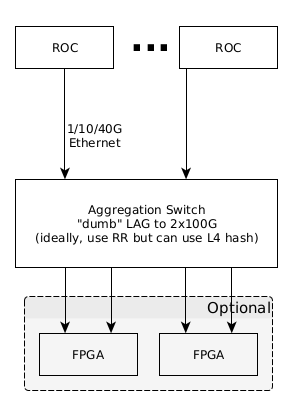
Data Source Aggregation Switch
Individual Data Source channels will be aggregated for maximum throughput by a switch using Link Aggregation Protocol (LAG) or similar where the network traffic downstream of the switch will be addressed to the LB FPGA (see (Figure X, Appendix X).
If the LAG configured switch proves to be incapable of meeting line rate throughput (100Gbs), then an additional FPGA(s) can be engineered to subsume this function as depicted in Figure X.
LB Processing
The FPGA resident LB aggregates data across all so designated source data channels for a single discrete tick and routes this aggregated data to individual end compute nodes in cooperation with the FPGA host chassis CPU using algorithms designed for the host CPU and feedback received from the end compute node farm, maintaining complete opacity of the UDP payload to the LB (except for the LB meta-data).

Load Balancer Pipeline API
link
Appendix: EJFAT Processing

Appendix: Network Path MTU Discovery support in the Linux Kernel
Enable Jumbo Frames
file: /proc/sys/net/ipv4/tcp_mtu_probing
variable: net.ipv4.tcp_mtu_probing (integer; default: 0; since Linux 2.6.17):

tcp_mtu_probing - INTEGER
	Controls TCP Packetization-Layer Path MTU Discovery.  Takes three values:
	  0 - Disabled
	  1 - Disabled by default, enabled when an ICMP black hole detected
	  2 - Always enabled, use initial MSS of tcp_base_mss.
Here's a quick update of where we got to Thu/Fri last week and this morning. Excellent progress, and proof of life throughout the design.
After a bit of investigation and bug fixing in the table programming code, the following things are confirmed working on indra-s2 as of Mon AM:
FPGA download using vivado labtools
docker compose up smartnic-hw
Note: we do not have root cause yet on why we sometimes have programming failures.
smartnic firmware environment is operational
docker compose up -d
docker compose exec smartnic-fw bash
regio syscfg
100G Link up between mellanox and U280 (cmac1)
ip -d link show enp59s0f1
ethtool enp59s0f1
regio cmac1
Packet Rx on U280 CMAC1
sudo tcpreplay -i enp59s0f1 ~/jlab/artifacts/sn-stack/pcaps/packets_in.pcap
regio probe_from_cmac_1
P4 table programming with sn-cli tool is working with unmodified p4bm runsim.txt files
sn-cli -p $REGIO_SELECT -c runsim.txt sdnet-config-apply
no need to reorder fields anymore -- fixed
bug in action parameter encoding discovered and fixed
Packet Tx from U280 CMAC1
regio probe_to_cmac_1
sudo tcpdump -i enp59s0f1 -w jlab-capture-05.pcap
Load balancer functionality confirmed for IPv4 and IPv6 test packets
tshark -r jlab-capture-05.pcap -V | less
udp load balance header popped
MAC DA rewritten
IPv4/IPv6 Dst IP rewritten
UDP Dst Port rewritten
Note: IPv4 header checksum and UDP header checksums are off by 1 in this load -- still investigating this
tshark -o ip.check_checksum:TRUE -o udp.check_checksum:TRUE -r jlab-capture-05.pcap -V | less
Let me know if you'd like clarification on any of these results or if you have any questions.
