Difference between revisions of "Gallery"
Jump to navigation
Jump to search
| (6 intermediate revisions by the same user not shown) | |||
| Line 1: | Line 1: | ||
<gallery> | <gallery> | ||
| − | + | file:Rackmove1.jpg | |
| + | File:Rackmove2.jpg | ||
| + | File:Rackmove3.jpg | ||
| + | File:Rackmove4.jpg | ||
| + | File:Rackmove5.jpg | ||
| + | File:Rackmove6.jpg | ||
| + | File:ssacm1.jpg | SSAs for CM 1 | ||
| + | File:ssapwr.jpg | AC power ready for the SSAs | ||
File:Pss1.jpg | PSS interlock chassis wiring progress | File:Pss1.jpg | PSS interlock chassis wiring progress | ||
File:Gallery2.jpg | Revised layout with Cryo control racks | File:Gallery2.jpg | Revised layout with Cryo control racks | ||
| Line 7: | Line 14: | ||
File:vvu.JPG | New "active" Voltage Verification Units (VVU) installed on 480VAC breaker panel | File:vvu.JPG | New "active" Voltage Verification Units (VVU) installed on 480VAC breaker panel | ||
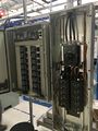
File:SSA Breaker.JPG | Location of first 8 Solid State Amplifiers & Breaker Panel | File:SSA Breaker.JPG | Location of first 8 Solid State Amplifiers & Breaker Panel | ||
| + | File:Water_manifold.jpg|Water manifold for SSAs & Circulators in both zones are installed in the gallery | ||
</gallery> | </gallery> | ||
Latest revision as of 09:52, 5 May 2018

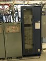
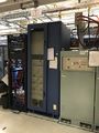
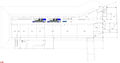
SSAs for CM 1
AC power ready for the SSAs
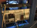
PSS interlock chassis wiring progress
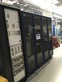
Revised layout with Cryo control racks
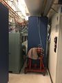
PLC for Cryogenic Control in Gallery
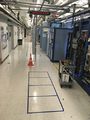
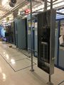
Location of Cryogenic Control Racks in Gallery
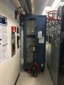
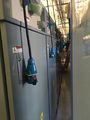
New "active" Voltage Verification Units (VVU) installed on 480VAC breaker panel
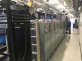
Location of first 8 Solid State Amplifiers & Breaker Panel
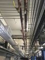
Water manifold for SSAs & Circulators in both zones are installed in the gallery


