Difference between revisions of "GTS meeting 10 04 16"
Jump to navigation
Jump to search
| Line 23: | Line 23: | ||
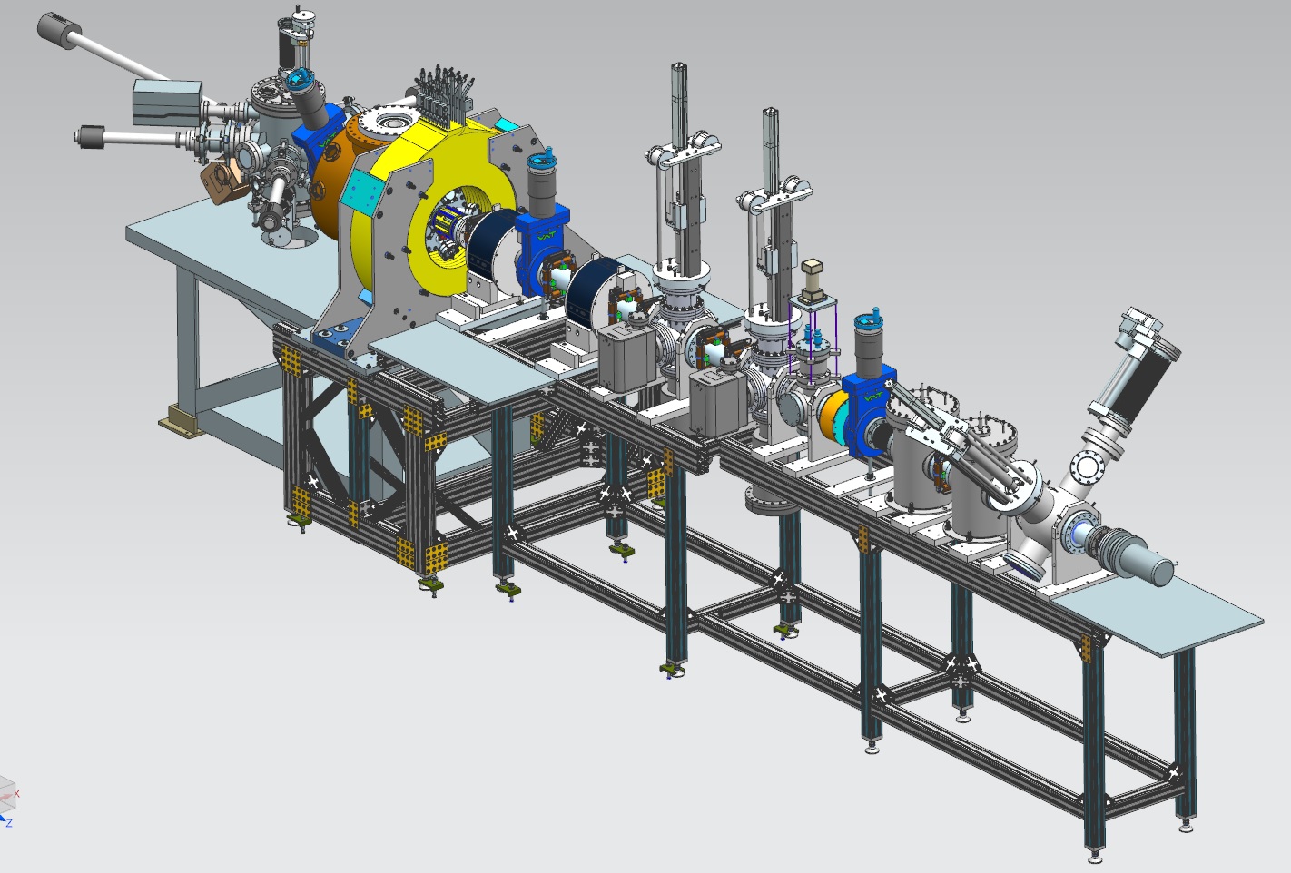
** [[File:Beamline with wire scanner ISO view.jpg]] | ** [[File:Beamline with wire scanner ISO view.jpg]] | ||
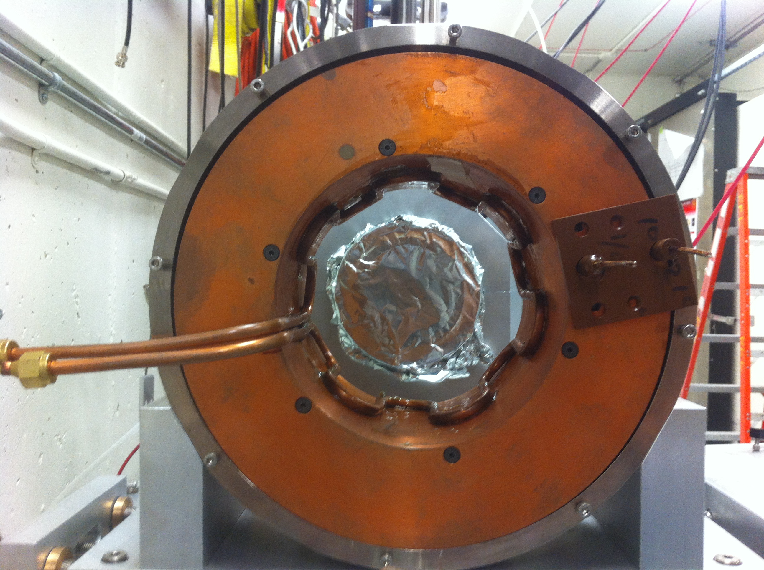
| − | + | ** The next picture shows the firs beam line solenoid without the steel plates, resting on its beam line mount. | |
| + | **[[File:Solenoid without steel plates.JPG]] | ||
* '''Gun HV chamber''' | * '''Gun HV chamber''' | ||
Latest revision as of 06:18, 5 October 2016
- Cathode prep chamber
- A new type of spring from a manufacturer has been ordered (free sample). The spring is Beryllium-copper.
- The top heater and the rod for the mask are being lengthened to accommodate the travel of the 150 mm translation manipulator.
- Mamun has been working on the Nb:CsK2Sb cathode QE vs wavelength at various temperatures
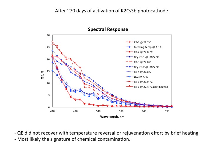
- Media:Bialkali Photocathode Update_100416.pptx
- Beam line / magnet
- Magnet is ready
- Power Supply is ready – operational current is 400 A and operational voltage is 77 V.
- Industrial Hygiene has performed a magnetic field survey. When solenoid is at 400 A, the medical boundary of 5 Gauss is 7 feet from the solenoid. The highest measurement of 2000 Gauss was taken within 6" of the solenoid. A 5 Gauss boundary sign will be posted at the door and a 600 Gauss boundary will be posted near the solenoid. Industrial Hygiene made the sings and are ready to post.
- Magnet and Power Supply interlocks:
- Magnet LCW flow (>4.00 GPM)
- Magnet temperature (<65 C)
- Power Supply Voltage (<79 V)
- Power Supply LCW flow (>1.25 GPM).
- Still to install: Concrete Door Interlock. There will be a Concrete Door Interlock bypass key to be able to enter GTS with magnet ON. When door interlock is bypassed, to prevent personnel with surgical implants and bioelectric devices from entering the 5 Gauss boundary, strobe light indicators are installed on the top of power supply and at the access door to show solenoid is energized as well as flashing red beacons and personnel barricades are installed at the actual 5 Gauss contour.
- A draft of magnet Operational Safety Procedure: media:MLDGT01_OSP.pdf
- First beamline tube – to be installed between gun and gate valve – has been removed to be modified by machine shop.
- LDRDS (Large Dynamic Range Diagnostic Station) will be installed in front of the dump (as a third diagnostic crossing).
- Gun HV chamber
- NEG cartridges have been mounted, but only 6 out of 8.
- The perforated plate has been dry-fitted
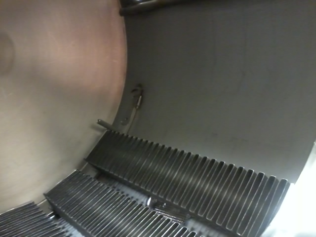
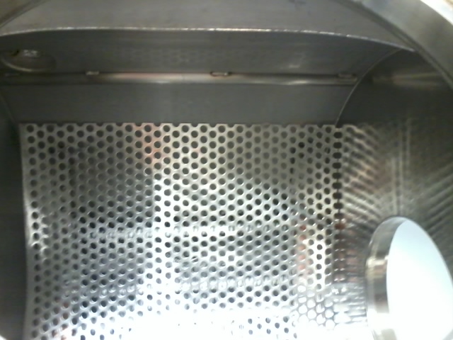
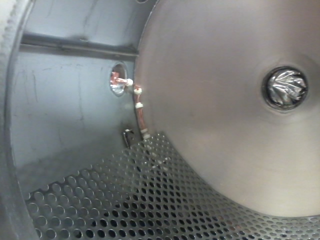
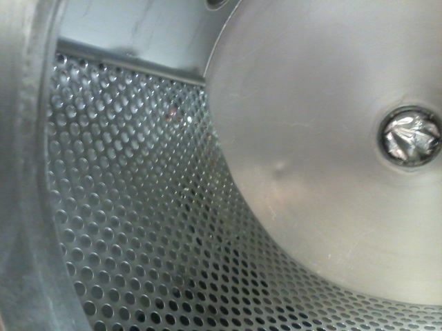
- The gun chamber has been baked at 250C with the NEG modules and the perforated screen only.
- The NEGs were activated, first to 15 Amps while the chamber was at 250C, then a second time to 22 Amps while the chamber was back at room temperature.
- The bake/activation cycle was performed to generate as much NEG dust as possible, which happens during the first two activation cycles per SAES paper.
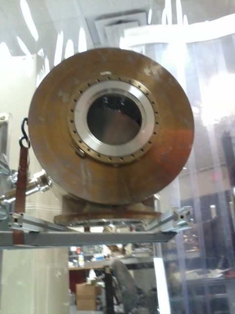
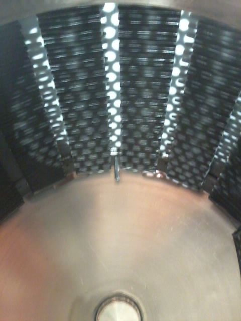
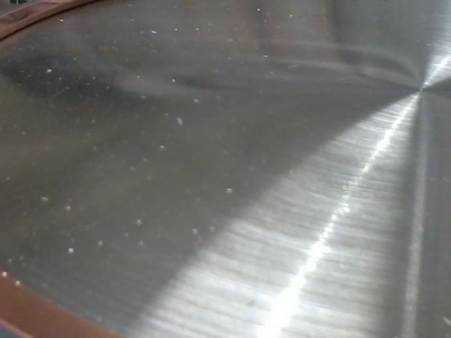
- We assembled the electrode and even trained Yan on how to do that job!
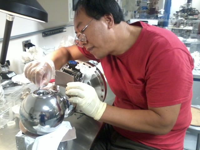
- But we realized that the SS ball electrode did not get aperture for the shed widened from 1.25 in diameter to 2.16 in diameter!, So Bubba brought over the Nb, barrel-polished ball electrode which we assembled using the SS Yan's design shed, and that is why the ball and the shed reflect light differently in the picture below.
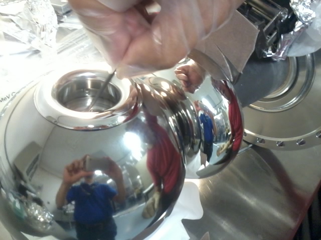
- BUT the Nb ball is about 1/8" smaller diameter than the SS ball. This means that the front and back cathode end piece cannot press hard enough against the ball, allowing it to be rotate around the puck axis of symmetry. This may lead to non0uniform gap between the ceramic and the shed, which in turns leads to nonuniform potential distribution leading to possible plug arcing.
- The SS ball is now at the machine shop for opening the shed aperture. Bubba will re-polished and clean it. In this way, we will have an electrode with all SS, barrel polished pieces,
