Difference between revisions of "Beam line"
Jump to navigation
Jump to search
(Created page with "* This is the field map for MFGGT01: Media:GTS Solenoid 001 Integrals.xlsx * This is the field map for MFGGT02: * This is the data sent by RadiaBeam for the steering magne...") |
|||
| (8 intermediate revisions by the same user not shown) | |||
| Line 1: | Line 1: | ||
| + | * CEBAF-type Harp mounted on 2-3/4" cross | ||
| + | **[[Media:CEBAF DIA Harp Assembly.pdf]] | ||
| + | **[[Media:CEBAF Harp Fork 45 degree assembly.pdf]] | ||
* This is the field map for MFGGT01: [[Media:GTS Solenoid 001 Integrals.xlsx]] | * This is the field map for MFGGT01: [[Media:GTS Solenoid 001 Integrals.xlsx]] | ||
| − | * This is the field map for MFGGT02: | + | * This is the field map for MFGGT02:[[Media:GTS Solenoid 002 Integrals.xlsx]] |
| − | * This is the data sent by RadiaBeam for the steering magnets MCRGT01, 02 and 03: | + | * This is the data sent by RadiaBeam for the steering magnets MCRGT01, 02 and 03:[[Media:RadiaBeam steerers testdata]] |
| + | * Beam line layout as of November 2016: [[Media:JL0038343-MAGNETIZED BEAM LDRD ASSY 4 solenoids.pdf]] | ||
| + | * Slit assembly drawing, the beam enters the flat part of the slit: [[Media:haysg_JL0035130-EMS SLIT SYSTEM ASSEMBLY.pdf]] | ||
| + | * Slits gap measured by S&A after Bubba "lapped" them to attain no gap w/o foil [[Media:Slits S&A gap measurements.pdf]] | ||
| + | * [[Media:YAG_facts.docx]] | ||
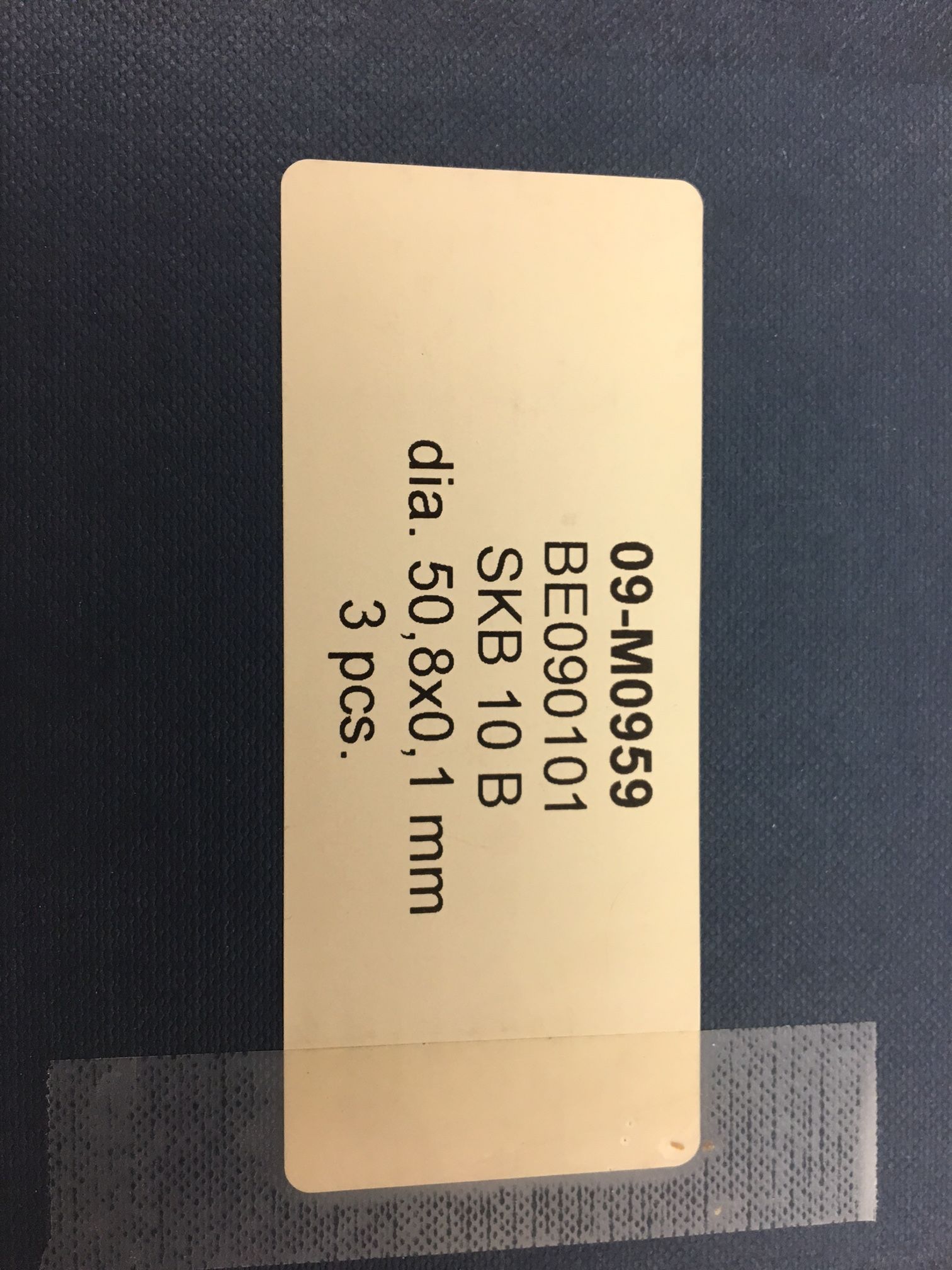
| + | * The YAG crystal is 100 um thick | ||
| + | * [[File:YAG screen is 100 um thick.jpeg]] | ||
Latest revision as of 09:05, 23 August 2017
- CEBAF-type Harp mounted on 2-3/4" cross
- This is the field map for MFGGT01: Media:GTS Solenoid 001 Integrals.xlsx
- This is the field map for MFGGT02:Media:GTS Solenoid 002 Integrals.xlsx
- This is the data sent by RadiaBeam for the steering magnets MCRGT01, 02 and 03:Media:RadiaBeam steerers testdata
- Beam line layout as of November 2016: Media:JL0038343-MAGNETIZED BEAM LDRD ASSY 4 solenoids.pdf
- Slit assembly drawing, the beam enters the flat part of the slit: Media:haysg_JL0035130-EMS SLIT SYSTEM ASSEMBLY.pdf
- Slits gap measured by S&A after Bubba "lapped" them to attain no gap w/o foil Media:Slits S&A gap measurements.pdf
- Media:YAG_facts.docx
- The YAG crystal is 100 um thick