Difference between revisions of "Cables"
| (8 intermediate revisions by the same user not shown) | |||
| Line 1: | Line 1: | ||
== Overview == | == Overview == | ||
[[File:QJLdFW.png|800px]] [[File:Overview.jpg|1300px]] | [[File:QJLdFW.png|800px]] [[File:Overview.jpg|1300px]] | ||
| + | |||
| + | The NPS calorimeter will be enclosed in a light-tight and temperature controlled box: | ||
| + | |||
| + | [[File:Box.jpg|800px]] | ||
| + | |||
== Voltage divider == | == Voltage divider == | ||
| Line 11: | Line 16: | ||
== Custom cable from voltage divider to PCB boards == | == Custom cable from voltage divider to PCB boards == | ||
| − | This cable carries the HV to the PMT divder and reads the anode signal. The cable has a female SAMTEC 5-pin connector [https://www.samtec.com/products/ipd1-05-s-k IPD1-05-S-K] on one side, with 4 crimp contacts [https://www.samtec.com/products/cc79l-2630-01-l CC79L-2630-01-L]. On the other side the cable has a [https://int.rsdelivers.com/product/rs-pro/r19-003-03-0332110ll/rs-pro-straight-50%cf%89-cable-mount-coaxial-connector/5463210 SMA RS PRO 546-3210] connector [[https://wiki.jlab.org/cuawiki/images/0/07/SMA_546_3210.pdf Datasheet], [https://wiki.jlab.org/cuawiki/images/f/fe/SMA_D%C3%A9nudage.pdf Crimp instructions]] (signal) and a [https://www.fischerconnectors.com/sites/default/files/specifications/tech_specs_full_1.7_oct17.pdf Fischer connector S 102 A 018] (HV). Both the HV and the anode cables are | + | This cable carries the HV to the PMT divder and reads the anode signal. The cable has a female SAMTEC 5-pin connector [https://www.samtec.com/products/ipd1-05-s-k IPD1-05-S-K] on one side, with 4 crimp contacts [https://www.samtec.com/products/cc79l-2630-01-l CC79L-2630-01-L]. On the other side the cable has a [https://int.rsdelivers.com/product/rs-pro/r19-003-03-0332110ll/rs-pro-straight-50%cf%89-cable-mount-coaxial-connector/5463210 SMA RS PRO 546-3210] connector [[https://wiki.jlab.org/cuawiki/images/0/07/SMA_546_3210.pdf Datasheet], [https://wiki.jlab.org/cuawiki/images/f/fe/SMA_D%C3%A9nudage.pdf Crimp instructions]] (signal) and a [https://www.fischerconnectors.com/sites/default/files/specifications/tech_specs_full_1.7_oct17.pdf Fischer connector S 102 A 018] (HV). Both the HV and the anode cables are coaxial RG174/U ([https://wiki.jlab.org/cuawiki/images/9/94/009_RJ_174u_datasheet.pdf datasheet]). The cable length is 375 mm. |
* [https://wiki.jlab.org/cuawiki/images/c/c7/C%C3%A2blage_Embase_Interface_%281%29.pdf Cable schematics] | * [https://wiki.jlab.org/cuawiki/images/c/c7/C%C3%A2blage_Embase_Interface_%281%29.pdf Cable schematics] | ||
* Picture of the cable: | * Picture of the cable: | ||
| Line 23: | Line 28: | ||
* The anode cable is plugged into a [https://www.digikey.com/product-detail/en/cinch-connectivity-solutions-johnson/142-0701-501/J569-ND/241109 SMA CINCH CONNECTIVITY 142-0701-501] | * The anode cable is plugged into a [https://www.digikey.com/product-detail/en/cinch-connectivity-solutions-johnson/142-0701-501/J569-ND/241109 SMA CINCH CONNECTIVITY 142-0701-501] | ||
* The anode signal gets out at the opposite side of the board through an identical connector [https://www.digikey.com/product-detail/en/cinch-connectivity-solutions-johnson/142-0701-501/J569-ND/241109 SMA CINCH CONNECTIVITY 142-0701-501] | * The anode signal gets out at the opposite side of the board through an identical connector [https://www.digikey.com/product-detail/en/cinch-connectivity-solutions-johnson/142-0701-501/J569-ND/241109 SMA CINCH CONNECTIVITY 142-0701-501] | ||
| − | * The HV enters through [https:// | + | * The HV enters through two 15-pin SAMTEC [https://www.samtec.com/products/ipbt-115-h1-t-d-k IPBT-115-H1-T-D-K] and one 8-pin SAMTEC [https://www.samtec.com/products/ipbt-108-h1-t-d-k IPBT-108-H1-T-D-K] connectors at the top of the board |
* The LED sitting in front of each PMT are controlled by a ribbon cable plugged at the bottom of the board to male 2x36-pin SAMTEC connector [https://www.samtec.com/products/tst-136-01-l-d TST-136-01-L-D] | * The LED sitting in front of each PMT are controlled by a ribbon cable plugged at the bottom of the board to male 2x36-pin SAMTEC connector [https://www.samtec.com/products/tst-136-01-l-d TST-136-01-L-D] | ||
* Board schematics: [https://wiki.jlab.org/cuawiki/images/a/a1/Carte_Interface_SMA_SMA.pdf Layout.pdf], [https://wiki.jlab.org/cuawiki/images/9/9c/Sch%C3%A9ma_Carte_Interface_SMA_SMA.pdf Connections.pdf], [https://wiki.jlab.org/cuawiki/images/a/aa/Nomenclature_a282A.xlsx Parts.xlsx] | * Board schematics: [https://wiki.jlab.org/cuawiki/images/a/a1/Carte_Interface_SMA_SMA.pdf Layout.pdf], [https://wiki.jlab.org/cuawiki/images/9/9c/Sch%C3%A9ma_Carte_Interface_SMA_SMA.pdf Connections.pdf], [https://wiki.jlab.org/cuawiki/images/a/aa/Nomenclature_a282A.xlsx Parts.xlsx] | ||
| − | [[File:GoWTJr.png|400px]] [[File:PIN0ca.jpg|260px]] | + | [[File:GoWTJr.png|400px]] [[File:PIN0ca.jpg|260px]] [[File:07_Test_Câble_Carte.jpg|285px]] |
| − | == HV | + | == HV cables == |
The PCBs are connected to a HV panel at the top of the NPS box through 20-AWG cables. Three cables per detector column: 2 cables have [https://wiki.jlab.org/cuawiki/images/c/ca/SAMTEC-pmsdx-xx-xxxx-x-xx.xx-x-xxx-mkt.pdf SAMTEC PMSD-15-206-K-15.40-D-LUS] connectors and 1 cable has [https://wiki.jlab.org/cuawiki/images/c/ca/SAMTEC-pmsdx-xx-xxxx-x-xx.xx-x-xxx-mkt.pdf PMSD-08-206-K-15.40-D-LUS] connectors | The PCBs are connected to a HV panel at the top of the NPS box through 20-AWG cables. Three cables per detector column: 2 cables have [https://wiki.jlab.org/cuawiki/images/c/ca/SAMTEC-pmsdx-xx-xxxx-x-xx.xx-x-xxx-mkt.pdf SAMTEC PMSD-15-206-K-15.40-D-LUS] connectors and 1 cable has [https://wiki.jlab.org/cuawiki/images/c/ca/SAMTEC-pmsdx-xx-xxxx-x-xx.xx-x-xxx-mkt.pdf PMSD-08-206-K-15.40-D-LUS] connectors | ||
| Line 62: | Line 67: | ||
=== HV panel === | === HV panel === | ||
| − | |||
| − | |||
| − | |||
The board is made of two 15-pin SAMTEC [https://www.samtec.com/products/ipbt-115-h1-t-d-k IPBT-115-H1-T-D-K] and one 8-pin SAMTEC [https://www.samtec.com/products/ipbt-108-h1-t-d-k IPBT-108-H1-T-D-K] for each detector column (associated with one PCB board) | The board is made of two 15-pin SAMTEC [https://www.samtec.com/products/ipbt-115-h1-t-d-k IPBT-115-H1-T-D-K] and one 8-pin SAMTEC [https://www.samtec.com/products/ipbt-108-h1-t-d-k IPBT-108-H1-T-D-K] for each detector column (associated with one PCB board) | ||
* Board schematics [http://www.jlab.org/~munoz/Distributeur_HT_V2.pdf Layout.pdf], [https://wiki.jlab.org/cuawiki/images/4/4e/Distributeur_HT_V2.pdf Connections.pdf], [https://wiki.jlab.org/cuawiki/images/7/7c/Nomenclature_b282B.xlsx Parts.xlsx] | * Board schematics [http://www.jlab.org/~munoz/Distributeur_HT_V2.pdf Layout.pdf], [https://wiki.jlab.org/cuawiki/images/4/4e/Distributeur_HT_V2.pdf Connections.pdf], [https://wiki.jlab.org/cuawiki/images/7/7c/Nomenclature_b282B.xlsx Parts.xlsx] | ||
| − | * [https://wiki.jlab.org/cuawiki/images/f/f2/05_C%C3%A2blage_Distribution_HT_Power_Supplies.pdf | + | * In order to provide HV to the NPS detector, one should plug into this panel ribbon cables with [https://wiki.jlab.org/cuawiki/images/c/ca/SAMTEC-pmsdx-xx-xxxx-x-xx.xx-x-xxx-mkt.pdf SAMTEC PMSD-15-206-K-15.40-D-LUS] and [https://wiki.jlab.org/cuawiki/images/c/ca/SAMTEC-pmsdx-xx-xxxx-x-xx.xx-x-xxx-mkt.pdf PMSD-08-206-K-15.40-D-LUS] connectors. Details are provided [https://wiki.jlab.org/cuawiki/images/f/f2/05_C%C3%A2blage_Distribution_HT_Power_Supplies.pdf here] |
[[File:20190711_104413.jpg|1000px]] | [[File:20190711_104413.jpg|1000px]] | ||
| Line 74: | Line 76: | ||
Made of 2x36-pin SAMTEC connectors [https://www.samtec.com/products/tst-136-01-l-d TST-136-01-L-D] (one per detector column, i.e. a total of 30) | Made of 2x36-pin SAMTEC connectors [https://www.samtec.com/products/tst-136-01-l-d TST-136-01-L-D] (one per detector column, i.e. a total of 30) | ||
* Board schematics: [https://wiki.jlab.org/cuawiki/images/b/bf/Distribution_LED.pdf Layout], [https://wiki.jlab.org/cuawiki/images/2/2b/Sch%C3%A9ma_Distribution_LED.pdf Connections.pdf], [https://wiki.jlab.org/cuawiki/images/3/34/Nomenclature_c282A.xlsx Parts.xlsx] | * Board schematics: [https://wiki.jlab.org/cuawiki/images/b/bf/Distribution_LED.pdf Layout], [https://wiki.jlab.org/cuawiki/images/2/2b/Sch%C3%A9ma_Distribution_LED.pdf Connections.pdf], [https://wiki.jlab.org/cuawiki/images/3/34/Nomenclature_c282A.xlsx Parts.xlsx] | ||
| + | |||
| + | == Tests performed on boards and cables == | ||
| + | * [https://wiki.jlab.org/cuawiki/index.php/Cables/Tests In French] (to be translated soon) | ||
Latest revision as of 07:33, 10 October 2020
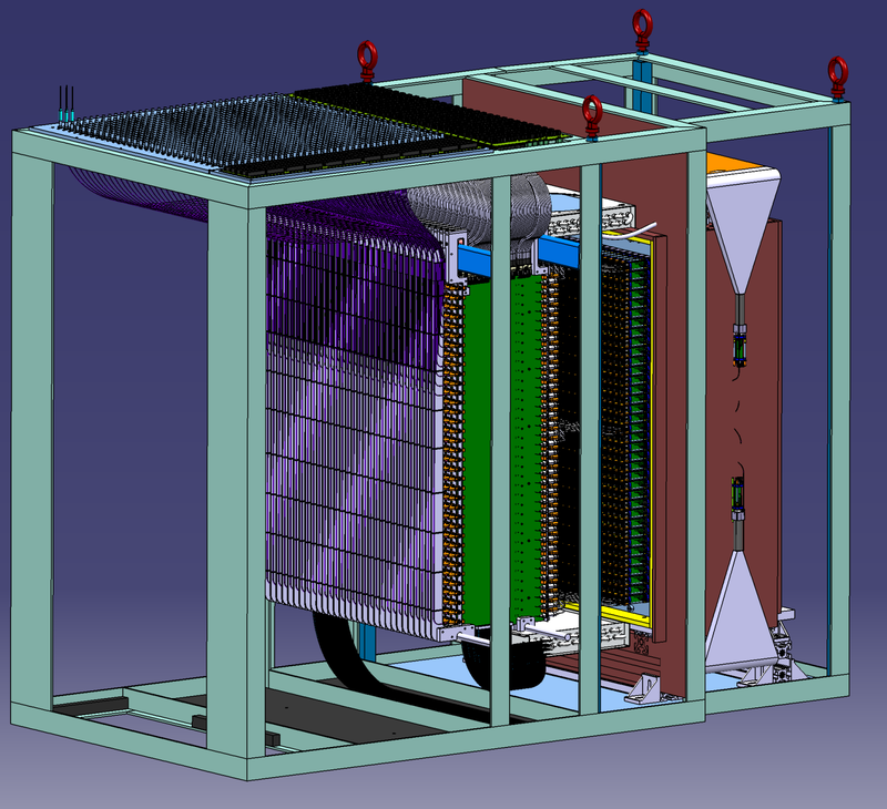
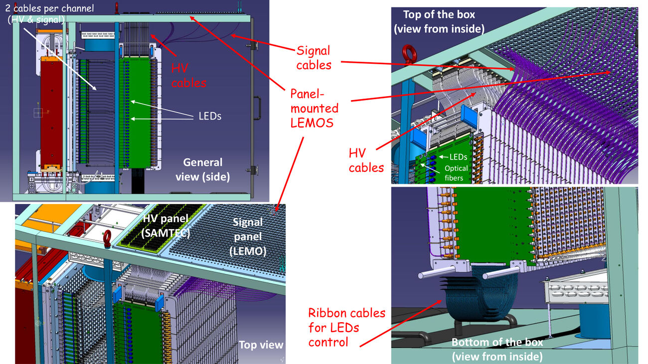
Overview
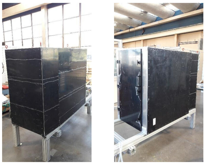
The NPS calorimeter will be enclosed in a light-tight and temperature controlled box:
Voltage divider
- Voltage divider schematics
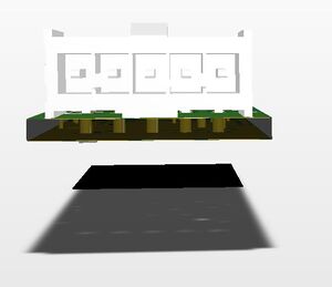
- The 5-pin connector on the voltage divider is Samtec Part # IPL1-105-01-L-S-RA-K (male):
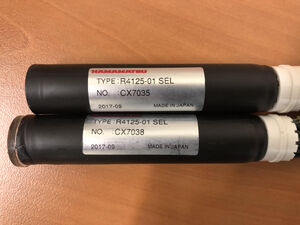
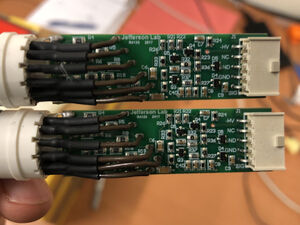
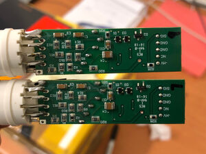
- Pictures of the assembly:
Custom cable from voltage divider to PCB boards
This cable carries the HV to the PMT divder and reads the anode signal. The cable has a female SAMTEC 5-pin connector IPD1-05-S-K on one side, with 4 crimp contacts CC79L-2630-01-L. On the other side the cable has a SMA RS PRO 546-3210 connector [Datasheet, Crimp instructions] (signal) and a Fischer connector S 102 A 018 (HV). Both the HV and the anode cables are coaxial RG174/U (datasheet). The cable length is 375 mm.
- Cable schematics
- Picture of the cable:
PCB boards (one per detector column)
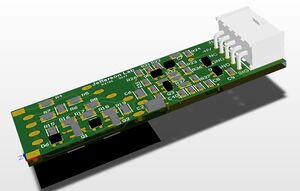
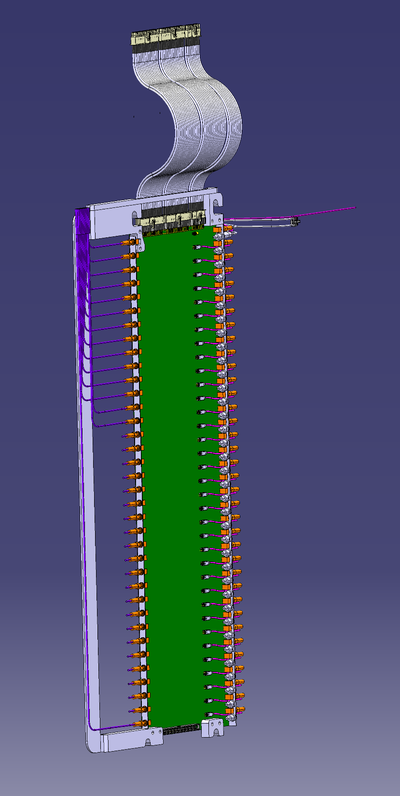
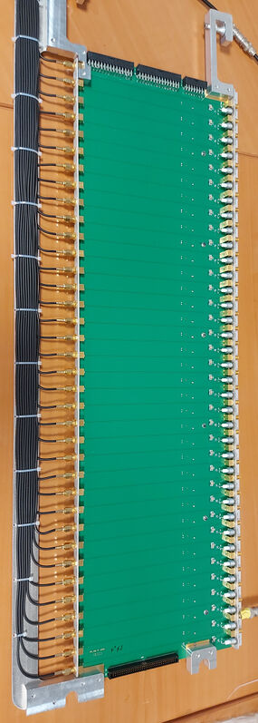
The HV and the anode signals of each column of the detector is routed through a PCB board. This boards also holds one LED per channel.
- Each HV cable is plugged into a Fischer D 102 A018 connector on the PCB board
- The anode cable is plugged into a SMA CINCH CONNECTIVITY 142-0701-501
- The anode signal gets out at the opposite side of the board through an identical connector SMA CINCH CONNECTIVITY 142-0701-501
- The HV enters through two 15-pin SAMTEC IPBT-115-H1-T-D-K and one 8-pin SAMTEC IPBT-108-H1-T-D-K connectors at the top of the board
- The LED sitting in front of each PMT are controlled by a ribbon cable plugged at the bottom of the board to male 2x36-pin SAMTEC connector TST-136-01-L-D
- Board schematics: Layout.pdf, Connections.pdf, Parts.xlsx
HV cables
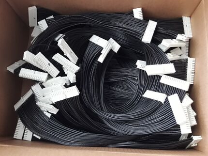
The PCBs are connected to a HV panel at the top of the NPS box through 20-AWG cables. Three cables per detector column: 2 cables have SAMTEC PMSD-15-206-K-15.40-D-LUS connectors and 1 cable has PMSD-08-206-K-15.40-D-LUS connectors
Notice that 20 AWG = 7.2 A, and our currents are of the order of micro-Amps.
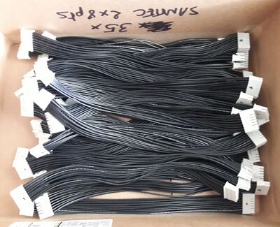
LED control cables
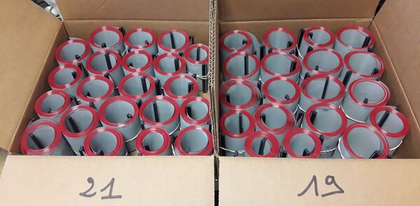
Ribbon cables with SAMTEC connectors HCSD-36-01-N on each side:
Anode signal cables
- Signal come out at the back of the PCB boards.
- There are KX3 cables with a SMA connector RS PRO 546-3210 on one side and a panel-mount LEMO PES.00.250.NTME31 on the other side
- The length of each cable depends on the row of the detector (longer cables for channels at the bottom).
- The LEMO connectors are mounted at the top of the NPS box (see LEMO panel below)
- Cable schematics
Patch panels at the top of the NPS box
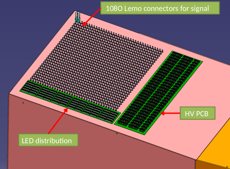
There are 3 panels on the top of the NPS box:
Signal panel (LEMO)
This is not patch panel per se, but a simple panel with holes where the LEMOSof the anode cables are mounted on.
HV panel
The board is made of two 15-pin SAMTEC IPBT-115-H1-T-D-K and one 8-pin SAMTEC IPBT-108-H1-T-D-K for each detector column (associated with one PCB board)
- Board schematics Layout.pdf, Connections.pdf, Parts.xlsx
- In order to provide HV to the NPS detector, one should plug into this panel ribbon cables with SAMTEC PMSD-15-206-K-15.40-D-LUS and PMSD-08-206-K-15.40-D-LUS connectors. Details are provided here
LED panel
Made of 2x36-pin SAMTEC connectors TST-136-01-L-D (one per detector column, i.e. a total of 30)
- Board schematics: Layout, Connections.pdf, Parts.xlsx
Tests performed on boards and cables
- In French (to be translated soon)
