Difference between revisions of "2018 Mott Paper Working Area"
| Line 29: | Line 29: | ||
::[[File:Asym_v_beampos_225.gif|600px]] | ::[[File:Asym_v_beampos_225.gif|600px]] | ||
::[[media:Asym v beampos final.ods]] | ::[[media:Asym v beampos final.ods]] | ||
| − | |||
| − | |||
=== Request #3 -- Ready for Review=== | === Request #3 -- Ready for Review=== | ||
| Line 37: | Line 35: | ||
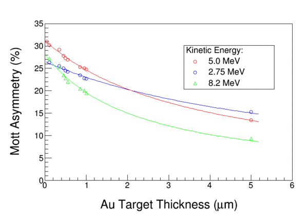
::[[File:Au_targetMSteigerwald.gif||600px]] | ::[[File:Au_targetMSteigerwald.gif||600px]] | ||
| − | === Request #4 === | + | === Request #4 -- Unanswered === |
We need an imagine of a typical FESEM picture showing a gold foil on a silicon substrate, or maybe 2 or 4 of them arranged to show typical measured you used in the analysis. | We need an imagine of a typical FESEM picture showing a gold foil on a silicon substrate, or maybe 2 or 4 of them arranged to show typical measured you used in the analysis. | ||
| − | === Request #5 === | + | === Request #5 -- Unanswered === |
For two foils, two samples were prepared – one near the foil center and one near the edge, and each were measured. Where are those results (or FESEM images) ? | For two foils, two samples were prepared – one near the foil center and one near the edge, and each were measured. Where are those results (or FESEM images) ? | ||
Revision as of 14:58, 4 November 2018
General Links/Documents
- Back to Mott Homepage CEBAF_MeV_Mott_Polarimeter
- Up-to-date Tech Notes, Paper Articles, etc. : Archived Documents
- Run 1
- Online Analysis Spreadsheet : media:run1database.ods
- Asymmetry vs Foil Thickness Full Analysis Spreadsheet : media:06.01.17_Run1_ARC+Dilution.ods
- Run 2
- Online Analysis Spreadsheet : Media:Run2RawData.ods
- Asymmetry vs Foil Thickness Full Analysis Spreadsheet : media:06.01.17_Run2_ARC+Dilution.ods
Draft Punchlist
Request #1 -- Ready for Review
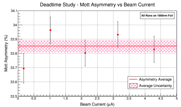
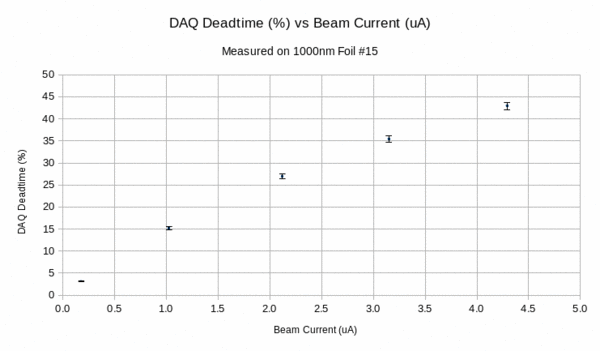
We measured dependence of electronic dead time on the beam current at five different average beam currents from 0.245-4.1 uA on a 1um foil. He'd like a plot showing the five data points vs. beam current with their individual uncertainties, and then the average with it's uncertainty band.
Request #2 -- Ready for Review
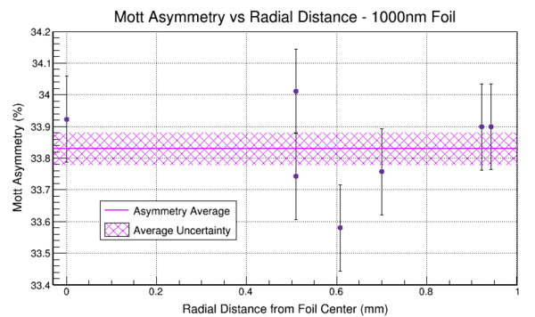
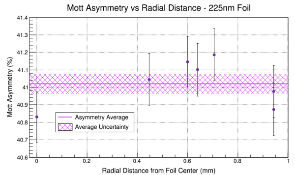
We measured dependence of the physics asymmetry on the position of the beam on the target foil from two target foils: 0.225um and 1um. For each foil we measured 7 asymmetries (one at center and six others away from center). The details are described in the systematics TN on the wiki. He'd like a plot showing the measured physics asymmetries (weighted average of IN/OUT) vs. radial distance from the center (instead of using x/y values shown in the TN), and then the average with it's uncertainty band, for the two target foils.
Request #3 -- Ready for Review
Recreate Michael's Paper's Plot: Remaking of Figure 6: media:Au_targetMSteigerwald.gif. The lines are a fit ( asym = a / (1.0 + alpha . d) ). On the original figure, the lines were his calculations.
Request #4 -- Unanswered
We need an imagine of a typical FESEM picture showing a gold foil on a silicon substrate, or maybe 2 or 4 of them arranged to show typical measured you used in the analysis.
Request #5 -- Unanswered
For two foils, two samples were prepared – one near the foil center and one near the edge, and each were measured. Where are those results (or FESEM images) ?
Request #6 -- Ready for Review
The detectors are centered at theta=172.6. We should check if S is maximum there or not. => The answer is that the maximum for KE=5MeV Au is 173.1 per Xavier and 129.9 per Ketevi. I think we erred perhaps so that the solid angle intercepted S at the same value left/right, or something like that.
- (Joe) Acceptance and Sherman Function media:160707_ShermancAcceptance.pptx
