Difference between revisions of "2018 Mott Paper Working Area"
| Line 59: | Line 59: | ||
== Request #8 -- Comparison of Absolute Detector Rate to Measured Detector Rate == | == Request #8 -- Comparison of Absolute Detector Rate to Measured Detector Rate == | ||
| + | ::*[[media:11.14.18 RunI RunII NormalizedRates.ods]] | ||
Revision as of 12:46, 14 November 2018
General Links/Documents
- Back to Mott Homepage CEBAF_MeV_Mott_Polarimeter
- Up-to-date Tech Notes, Paper Articles, etc. : Archived Documents
- Run 1
- Online Analysis Spreadsheet : media:run1database.ods -- Spreadsheet compiled while gathering data during Run I. Can be used as look-up table to determine which runs were used for which study. Asymmetry and rate numbers contained within are from preliminary analysis that does not include cuts, background handling etc. and so should not be referenced as final numbers.
- Asymmetry vs Foil Thickness Full Analysis Spreadsheet : media:06.01.17_Run1_ARC+Dilution.ods -- Final analysis numbers contained within, to be used and referenced in paper. ARC = Asymmetry, Rate, and Cuts; i.e. the full-detail analysis from raw ROOT file to final numbers.
- Run 2
- Online Analysis Spreadsheet : Media:Run2RawData.ods -- Spreadsheet compiled while gathering data. Can be used as look-up table to determine which runs were used for which study. Asymmetry and rate numbers contained within are from preliminary analysis that does not include cuts, background handling etc. and so should not be referenced as final numbers.
- Asymmetry vs Foil Thickness Full Analysis Spreadsheet : media:06.01.17_Run2_ARC+Dilution.ods -- Final analysis numbers contained within, to be used and referenced in paper. ARC = Asymmetry, Rate, and Cuts; i.e. the full-detail analysis from raw ROOT file to final numbers.
Draft Punchlist
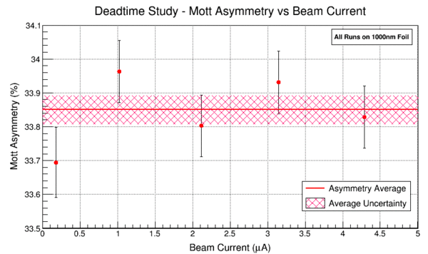
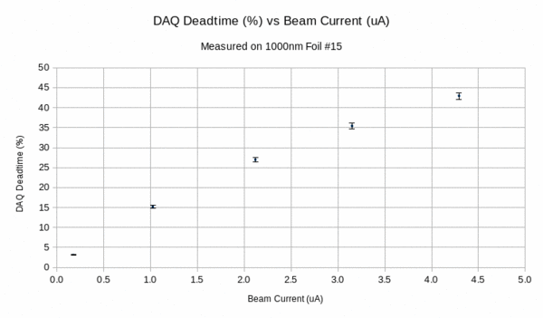
Request #1 -- Beam Current vs. Deadtime
We measured dependence of electronic dead time on the beam current at five different average beam currents from 0.245-4.1 uA on a 1um foil. He'd like a plot showing the five data points vs. beam current with their individual uncertainties, and then the average with it's uncertainty band.
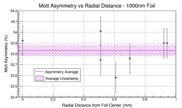
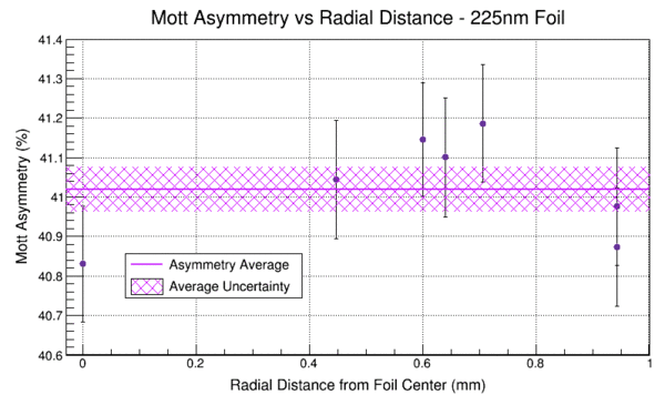
Request #2 -- Measured Asymmetry vs. Beam Position on Target
We measured dependence of the physics asymmetry on the position of the beam on the target foil from two target foils: 0.225um and 1um. For each foil we measured 7 asymmetries (one at center and six others away from center). The details are described in the systematics TN on the wiki. He'd like a plot showing the measured physics asymmetries (weighted average of IN/OUT) vs. radial distance from the center (instead of using x/y values shown in the TN), and then the average with it's uncertainty band, for the two target foils.
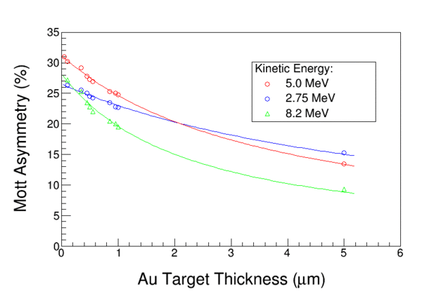
Request #3 -- Plot of Asymmetry vs. Target Thickness from SPIN 2000
Recreate Michael's Paper's Plot: Remaking of Figure 6: media:Au_targetMSteigerwald.gif. The lines are a fit ( asym = a / (1.0 + alpha . d) ). On the original figure, the lines were his calculations.
Request #4 -- Example of FESEM Image
We need an imagine of a typical FESEM picture showing a gold foil on a silicon substrate, or maybe 2 or 4 of them arranged to show typical measured you used in the analysis.
=> Here are some examples of foil thickness, which set of foils would be interesting to use? => Media:foil_Thickness_status-5June2015B.pptx
Request #5 -- Comparison of FESEM thickness vs foil position
For two foils, two samples were prepared – one near the foil center and one near the edge, and each were measured. Where are those results (or FESEM images) ?
=> Here is the summary of the measurements where two foils have "edge" and "center" values, is this sufficient ? Media:Summary_all_foils_5June2015C.xlsx
Request #6 -- Ready for Review
The detectors are centered at theta=172.6. We should check if S is maximum there or not. => The answer is that the maximum for KE=5MeV Au is 173.1 per Xavier and 129.9 per Ketevi. I think we erred perhaps so that the solid angle intercepted S at the same value left/right, or something like that.
- (Joe) Acceptance and Sherman Function media:160707_ShermancAcceptance.pptx
Request #7 -- Absolute Calibration of BCM0L02 to FC#2
- Run I -- BCM0L02 calibrated against FC#2 Elog -- https://logbooks.jlab.org/entry/3317350
- Run I -- First pass of calibrating Mott DAQ BCM VtoF Scaler vs BCM0L02 Elog --https://logbooks.jlab.org/entry/3322253
- Run II -- BCM0L02 calibrated against FC#2 Elog -- https://logbooks.jlab.org/entry/3354810
- Run II -- First pass of calibrating Mott DAQ BCM VtoF Scaler vs BCM0L02 Elog -- https://logbooks.jlab.org/entry/3354815
For the final analysis, rather than use a subset of Mott runs during a given Run period to calibrate the Mott DAQ BCM VtoF, all runs in a given Run period were used. That is, all runs in a given Run period BCM VtoF were plotted again BCM0L02 in order to determine appropriate calibration values for the VtoF signal. Then this VtoF calibrated current measure is used in the final analysis when calculating rates.
- Run I and II Final calibrations of Mott BCM VtoF scaler against BCM0L02 Elog -- https://logbooks.jlab.org/entry/3449037
